Video picture display unit

a video picture and display unit technology, applied in ventilation systems, electrical apparatus casings/cabinets/drawers, instruments, etc., can solve the problems of offensive to the user's ears, adverse influence of video picture display units, etc., to reduce the number of fans, reduce the number of revolutions, and reduce the discomfor

Inactive Publication Date: 2006-04-20
ORION ELECTRIC CO LTD
View PDF2 Cites 8 Cited by
  • Summary
  • Abstract
  • Description
  • Claims
  • Application Information

AI Technical Summary

Benefits of technology

[0005] It is therefore an object of the invention to provide a video picture display unit capable of reducing discomfort given to a user by restraining the influence of the noise of fans upon to the user after the power of the unit is turned off.
[0006] To achieve the above object, the video picture display unit of the invention comprises a display processing part for displaying video picture on a display part, fans for cooling a heat source of the display processing part, driving means for rotatably driving the fans, and a controller for driving and controlling the driving means, characterized in that the controller includes decision means for deciding presence or non-presence of timer setting when a power is turned off, and fan control means for driving and controlling the driving means so as to reduce the number of revolutions of the fans after a power-off processing in cases where the decision means decides the presence of the timer setting. Further, the fan control means is characterized in controlling the driving means so as to decrease the number of revolutions of the fans in stages.
[0007] With the arrangement of the video picture display unit as set forth above, in cases where the decision means decides the presence of timer setting when the power is turned off, the fan control means controls the driving means so as to decrease the number of revolutions of the fans after the power off processing, so that the noise of the fans is lowered after the power is turned off, thereby restraining the influence of the noise. Particularly, in a serene environment such as in a house, and the like, the noise generated by the fans is prone to be offensive to a user's ear, it is possible to minimize the influence of the noise upon the serene environment at the maximum by reducing the number of revolutions of the fans. Further, if the decision means decides the presence or non-presence of time setting when the power is turned off, it is possible to reduce discomfort given to the user by minimizing the noise of the fans at the time of sleeping of the user because timer setting frequently occurs when the power is turned off at the time of sleeping of the user.
[0008] Still further, if the fan control means controls the number of revolutions of the fans so as to be decreased in stages, it is possible to reduce the noise of the fans in a state where cooling efficient is maintained. That is, since the heat is continuously radiated from the heat source immediately after the power is turned off, and if the number of revolutions is abruptly decreased in this state, accumulation of heat from the heat source develops, there arises a possibility of adverse influence upon the video picture display unit. However, if the number of revolutions is decreased in stages, it is possible to reduce the noise by sequentially decreasing the number of revolutions while sufficiently cooling the heat from the heat source immediately after the power if turned off.

Problems solved by technology

Particularly, in a serene environment such as in a house, and the like, the noise generated by the fans is prone to be offensive to a user's ear, it is possible to minimize the influence of the noise upon the serene environment at the maximum by reducing the number of revolutions of the fans.
That is, since the heat is continuously radiated from the heat source immediately after the power is turned off, and if the number of revolutions is abruptly decreased in this state, accumulation of heat from the heat source develops, there arises a possibility of adverse influence upon the video picture display unit.

Method used


Image

  • Video picture display unit
  • Video picture display unit
  • Video picture display unit

Examples


Embodiment Construction

[0016] An embodiment of the invention is now described more in detail. Since the embodiment described hereinafter is a preferred concrete example to work the invention, it is variously limited in technical point of view, but the invention is not limited to the embodiment unless explicitly limiting thereto.

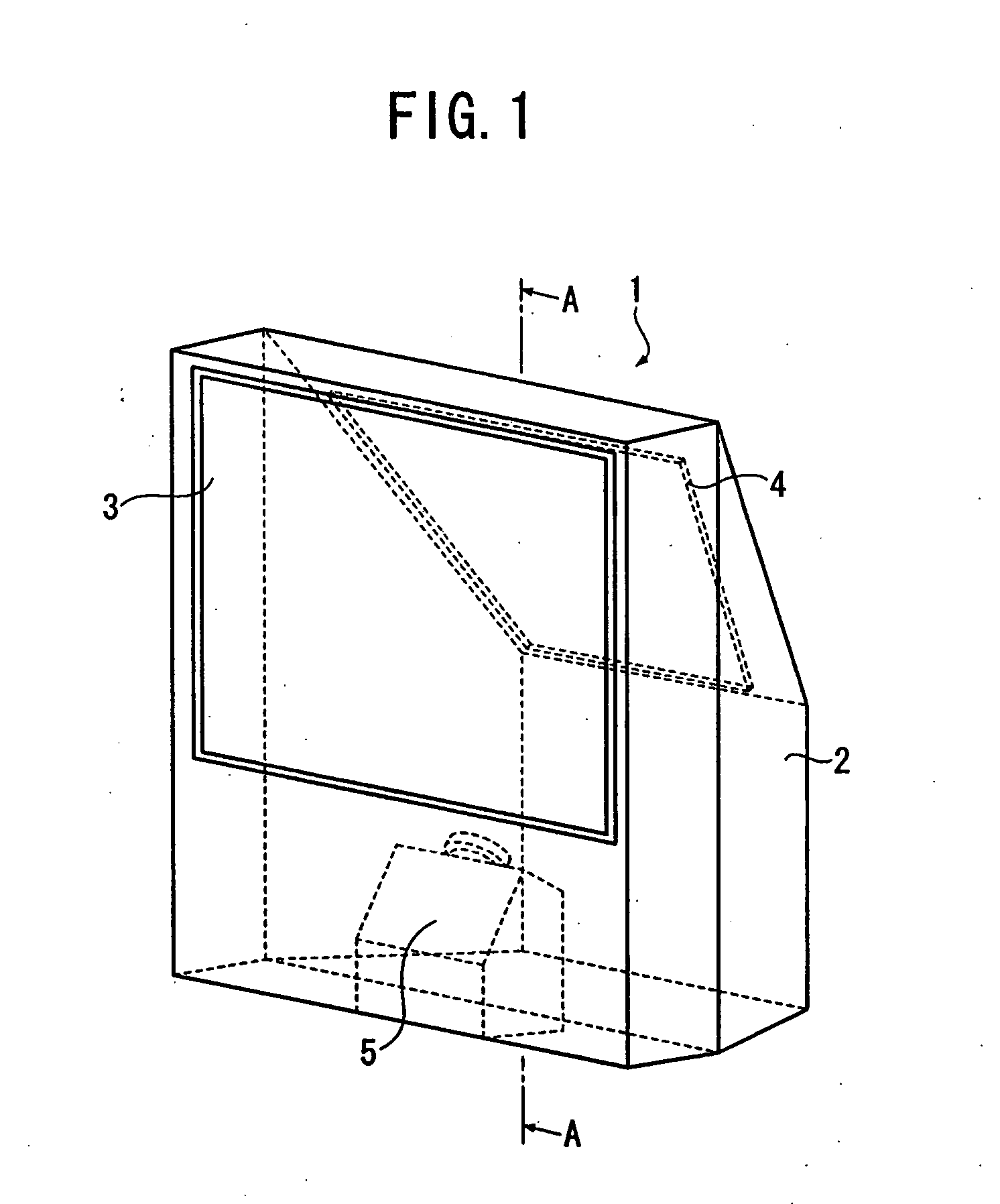
[0017]FIG. 1 is a schematic entire perspective view of a rear projection unit of an embodiment according to the invention. A rear projection unit 1 has a screen 3 fitted to a front face of a body housing 2 and a reflection mirror 4 fitted to a rear face of the body housing 2 while inclined toward the screen 3. An optical unit 5 is disposed on a bottom face of the body housing 2. A video picture emitted from the optical unit 5 is reflected off the screen 3 through the reflection mirror 4, and it is projected onto the rear face of the screen 3, then displayed on the front face of the screen 3.

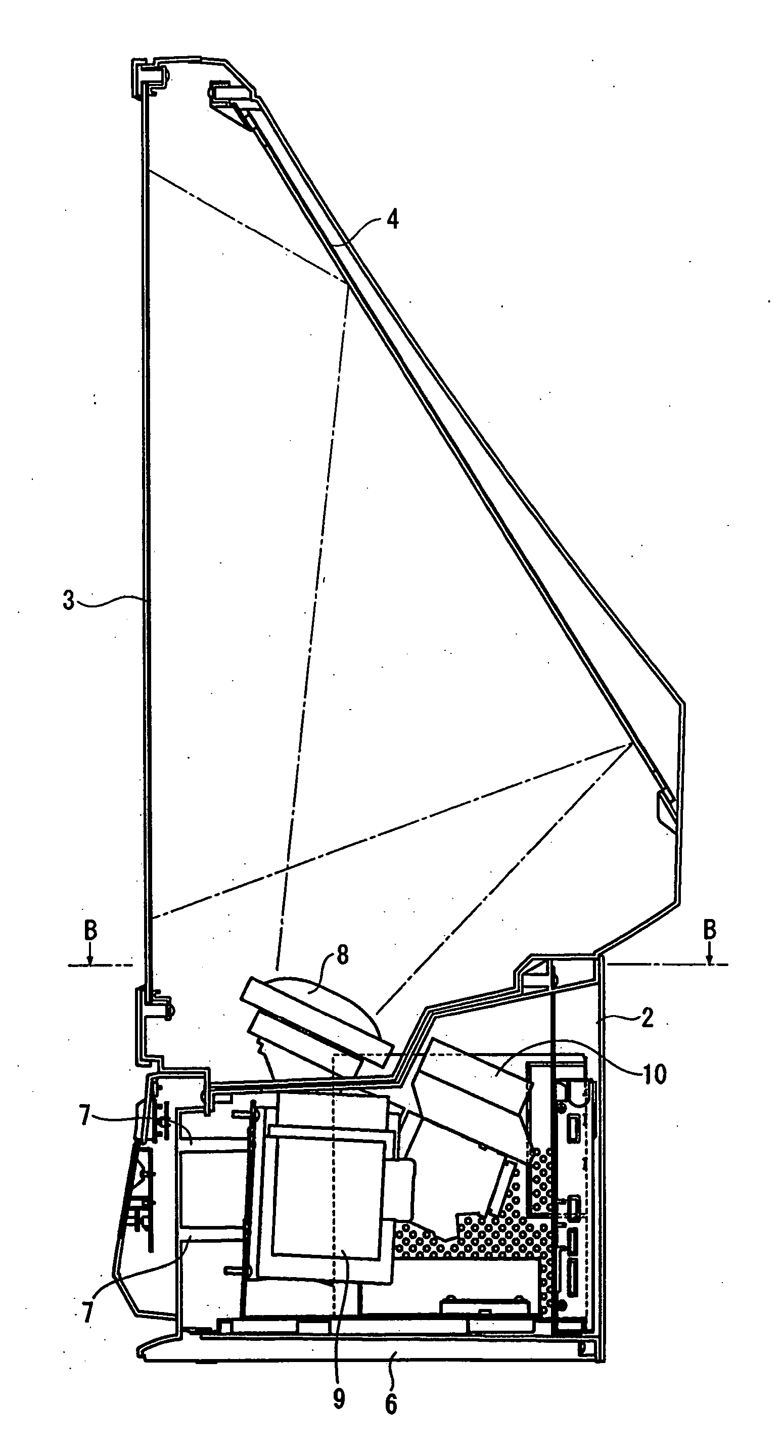
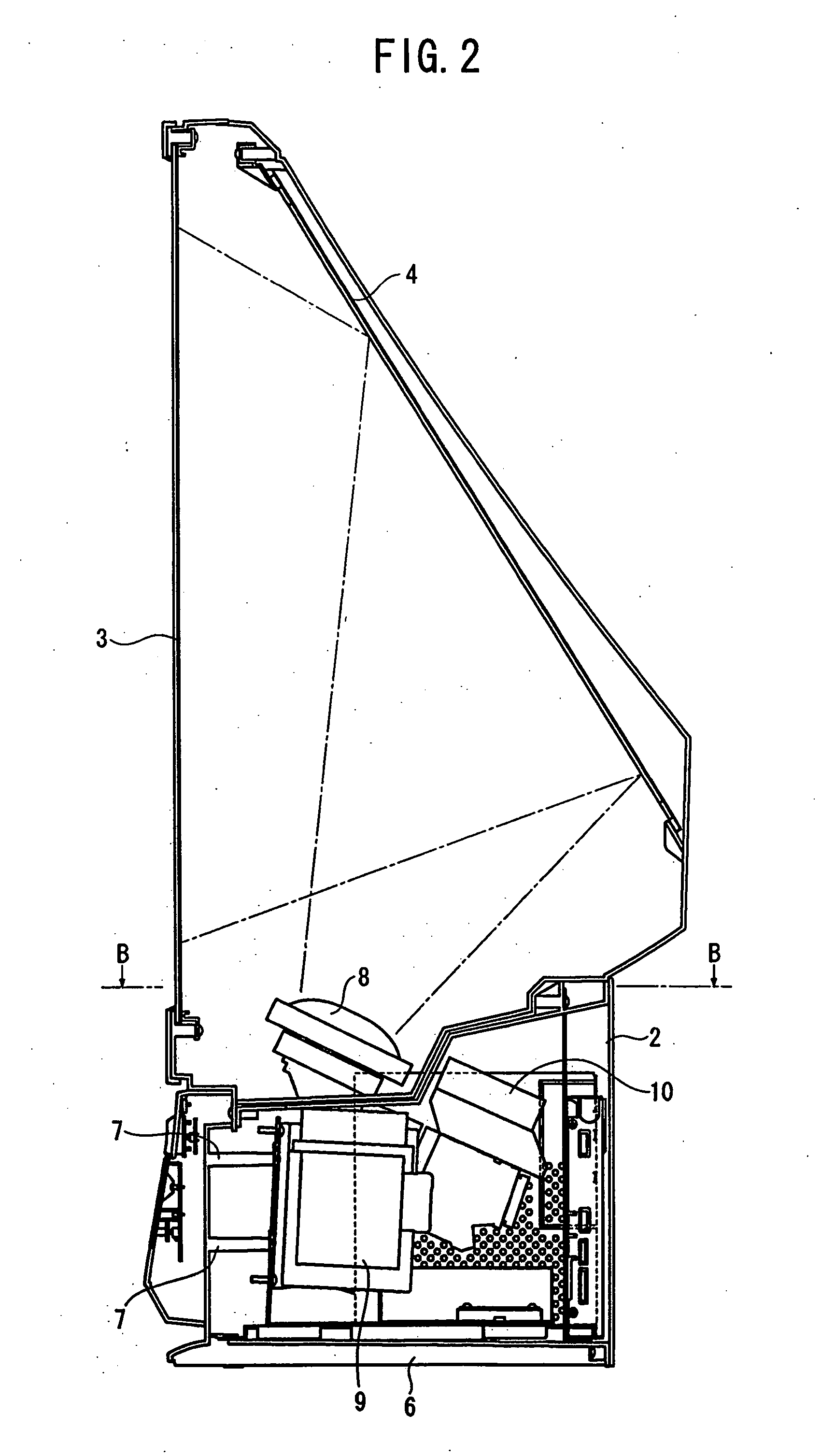
[0018]FIG. 2 is a view of the rear projection unit taken along A-A in FIG. 1 as viewed fro...


PUM


Abstract

The invention is to provide a video picture display unit capable of reducing discomfort given to a user by restraining influence of a noise of fans after the power of the unit is turned off. A timer setting when the power is turned off (off timer setting or sleep setting) is stored in a setting portion of a controller. A decision portion decides as to whether the timer setting is present or non-present, and in cases where the power is turned off by the timer setting, the operation control portion transmits a control signal to a driving circuit so as to cause a fan or a fan to effect low speed rotating operation.

Description

FIELD OF THE INVENTION [0001] The invention relates to a video picture display unit such as a television set like a projection television and so forth, a projection unit such as a projector, and a recorded picture reproducing display unit provided with a VCR, a DVD or an HDD or the like for displaying video picture sound information and the like. BACKGROUND OF THE INVENTION [0002] Inasmuch as the foregoing video picture display unit uses a high voltage for clearly displaying a video picture, a large quantity of heat is generated, so that there has been employed a fan serving as cooling means for restraining the influence of such a heat. There is a likelihood of using a plurality of fans because the heat thus can be efficiently escaped or radiated to the outside by blowing air to a heat source while rotating the fans, and a cost is reduced. However, there occurs frequently that the video picture display unit can be installed in a serene environment such as in a house, which causes a ...

Claims


Application Information

Patent Timeline
Patent Type & Authority Applications(United States)
IPC IPC(8): F24F13/06G06F1/16G05D23/00
CPCG03B21/10G03B21/16H04N9/3141
Inventor TANIGUCHI, TOSHIKAZUSEO, TOSHITAKA
Owner ORION ELECTRIC CO LTD
Why Eureka
Try Eureka