
Non-pneumatic tire

a non-pneumatic and tire technology, applied in the field of vehicles tires and non-pneumatic tires, can solve the problems of requiring compressed gas, pneumatic tires, and conventional pneumatic tires being rendered useless

Active Publication Date: 2017-10-19
THE GOODYEAR TIRE & RUBBER CO
View PDF1 Cites 13 Cited by
  • Summary
  • Abstract
  • Description
  • Claims
  • Application Information

AI Technical Summary

Benefits of technology

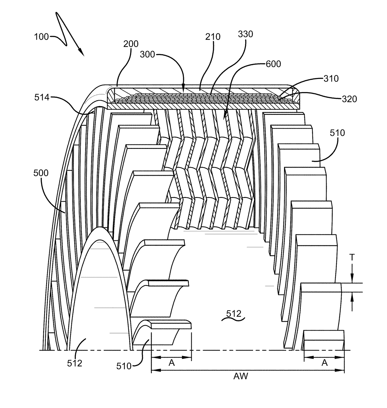
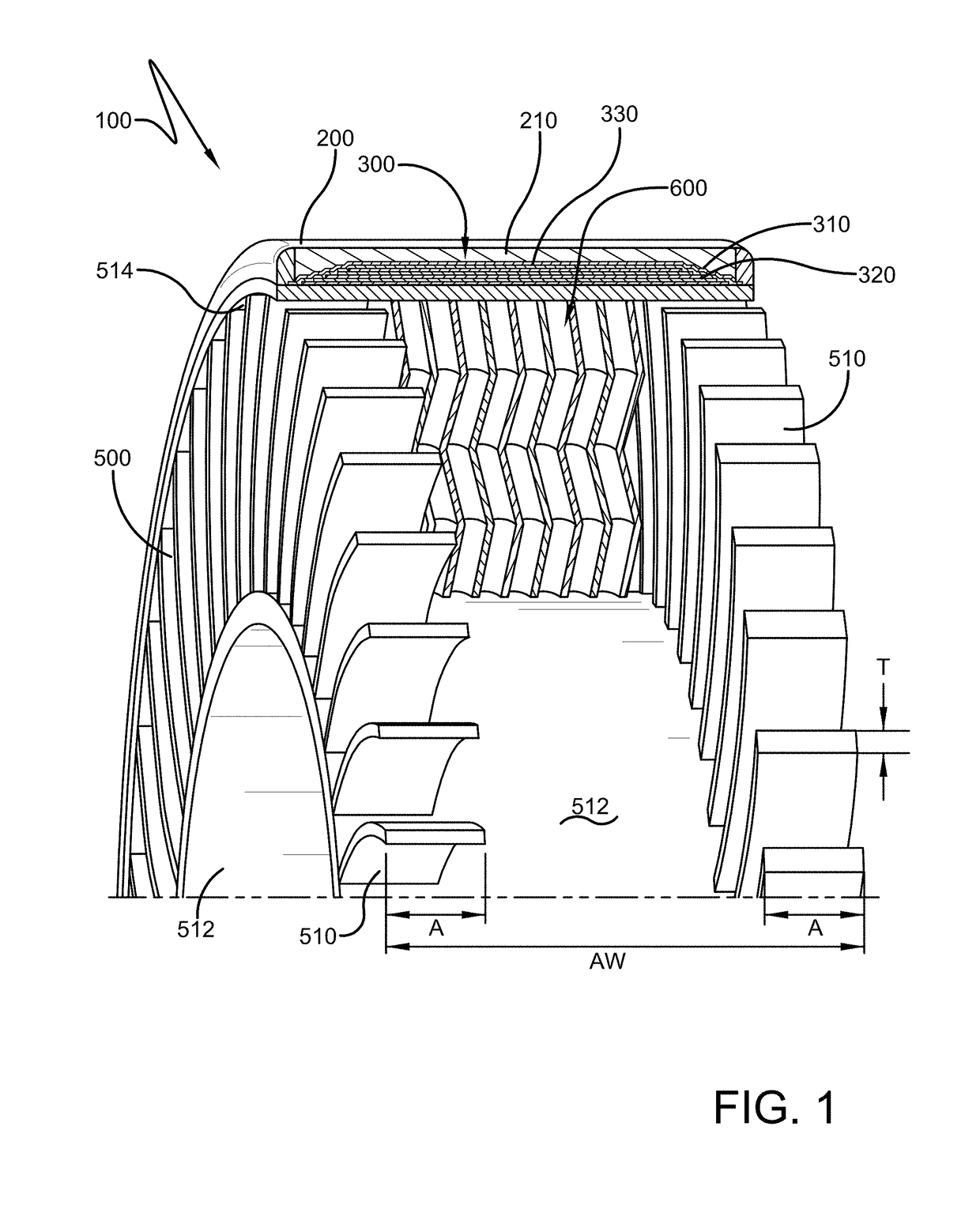
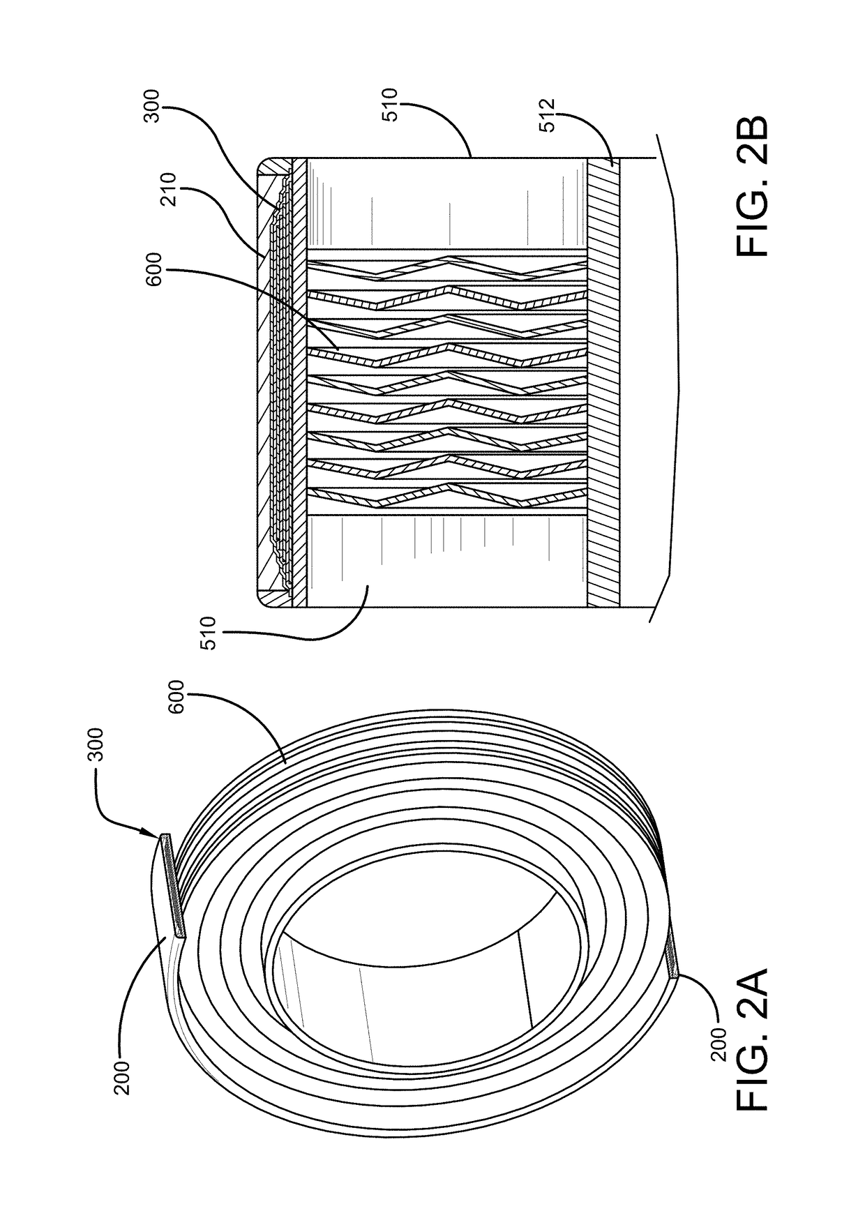
The present invention is about a non-pneumatic tire that can operate without inflation pressure. The invention aims to solve the problems associated with pneumatic tires such as the need for air inflation and the drawbacks of rubber materials. The non-pneumatic tire has a load carrying efficiency that is similar to pneumatic tires, but without the drawbacks of rubber. The invention includes a shear band that transfers the load from contact with the ground through tension in the spokes or connecting web to the hub, creating a top loading structure. The non-pneumatic tire has all the features of pneumatic tires without the need for air inflation. The invention also includes various configurations of the fabric structure of the non-pneumatic tire.

Problems solved by technology

The primary drawback to a pneumatic tire is that it requires compressed gasses.
A conventional pneumatic tire is rendered useless after a complete loss of inflation pressure.
Structurally supported tires such as solid tires or other elastomeric structures to date have not provided the levels of performance required from a conventional pneumatic tire.
The disadvantage to this type of construction is that the use of rubber significantly increases the cost and weight of the non-pneumatic tire.
Another disadvantage to the use of rubber is that is generates heat, particularly in the shear band.
Furthermore, the rubber in the shear band needs to be soft in shear, which makes it difficult to find the desired compound.

Method used


Image

  • Non-pneumatic tire
  • Non-pneumatic tire
  • Non-pneumatic tire

Examples


embodiment 500

[0044]An alternate embodiment 500 of the three dimensional structure is shown in FIG. 8, and comprises a first woven layer 560 of fabric, and a second woven layer 570 of fabric. The first and second layers are joined together by a plurality of cross members 580 formed in the shape of an “8”.

embodiment 700

[0045]An alternate embodiment 700 of the three dimensional structure is shown in FIGS. 9-10, and comprises a first woven layer 760 of fabric, and a second woven layer 770 of fabric. The first and second layers are joined together by a plurality of cross members 780. The first and second layers 760,770 have an open cell construction.

[0046]An alternate embodiment 800 of the three dimensional structure is shown in FIG. 11. The seventh embodiment 800 of the three dimensional structure comprises two or more deck layers 810,820. The seventh embodiment 800 has a first woven layer 860 of fabric, a second woven layer 870 of fabric, and a middle woven layer 880. The first and middle layers 860,880 are joined together by a plurality of cross members 890. The second and middle layers 870,880 are also joined together by a plurality of cross members 895. The cross members 890,895 may be angled or curved as shown in FIGS. 4-8.

[0047]The radial spokes may each be formed of two layers of three dimens...


PUM


Abstract

A non-pneumatic tire is described that includes a ground contacting annular tread portion, a shear band, wherein the shear band is formed of a first and second inextensible layer, and a low modulus material positioned between the first and second inextensible layer. The non-pneumatic tire further includes a connecting web positioned between a hub and the shear band, wherein the connecting web is formed of one or more spokes extending from an inner ring to an outer ring, wherein the one or more spokes are formed from a material reinforced with a three dimensional spacer structure.

Description

FIELD OF THE INVENTION[0001]The present invention relates generally to vehicle tires and non-pneumatic tires, and more particularly, to a non-pneumatic tire.BACKGROUND OF THE INVENTION[0002]The pneumatic tire has been the solution of choice for vehicular mobility for over a century. The pneumatic tire is a tensile structure. The pneumatic tire has at least four characteristics that make the pneumatic tire so dominant today. Pneumatic tires are efficient at carrying loads, because all of the tire structure is involved in carrying the load. Pneumatic tires are also desirable because they have low contact pressure, resulting in lower wear on roads due to the distribution of the load of the vehicle. Pneumatic tires also have low stiffness, which ensures a comfortable ride in a vehicle. The primary drawback to a pneumatic tire is that it requires compressed gasses. A conventional pneumatic tire is rendered useless after a complete loss of inflation pressure.[0003]A tire designed to opera...

Claims


Application Information

Patent Timeline
IPC IPC(8): B60C7/10
CPCB60C7/102B60C7/00B60C7/22B60C9/1807B60C7/14B60C7/18B60C7/143B60C7/20B60C7/146B60C7/107
Inventor TALBOT, WILLIAM ALAINBILGER, NICOLAS CHARLES LOUISSPORTELLI, FRANCESCOMZABI, SAMY LAROUSSISILL, CLEMENS MANUELKULIG, JOSEPH JOHNBONNET, GILLESWILMS, STEFAN
Owner THE GOODYEAR TIRE & RUBBER CO
Learn More