
Belt Tongue Comprising A Torsion Bar

a torsion spring and belt tongue technology, applied in the field of belt tongues, can solve the problem that the force applied by the torsion spring is not sufficient to release the blocking position

Active Publication Date: 2017-10-19
AUTOLIV DEV AB
View PDF15 Cites 11 Cited by
  • Summary
  • Abstract
  • Description
  • Claims
  • Application Information

AI Technical Summary

Benefits of technology

The patent text describes a belt tongue for a seatbelt that includes guide sections and a clamping element for securely positioning the tongue in the seatbelt. The guide sections are located in the region of the clamping element and are designed to reduce the structural height of the belt tongue in its insertion position. The clamping element itself is formed by bonding a spring element with the tongue body, simplifying the installation process. The tongue is designed to prevent self-clamping and to allow for reversible positioning between the clamping element and the seatbelt. Additionally, the belt webbing is guided through the tongue body only once, which prevents the formation of a loop and ensures proper positioning of the belt webbing.

Problems solved by technology

This results in the disadvantage that in a stressed position, the force applied by the torsion spring is not sufficient to release the blocking position caused by the pinched belt webbing.

Method used


Image

  • Belt Tongue Comprising A Torsion Bar
  • Belt Tongue Comprising A Torsion Bar
  • Belt Tongue Comprising A Torsion Bar

Examples


first embodiment

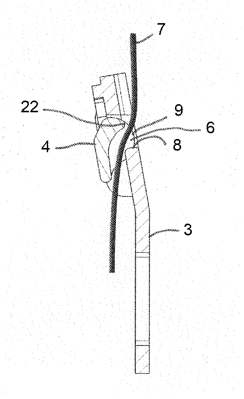
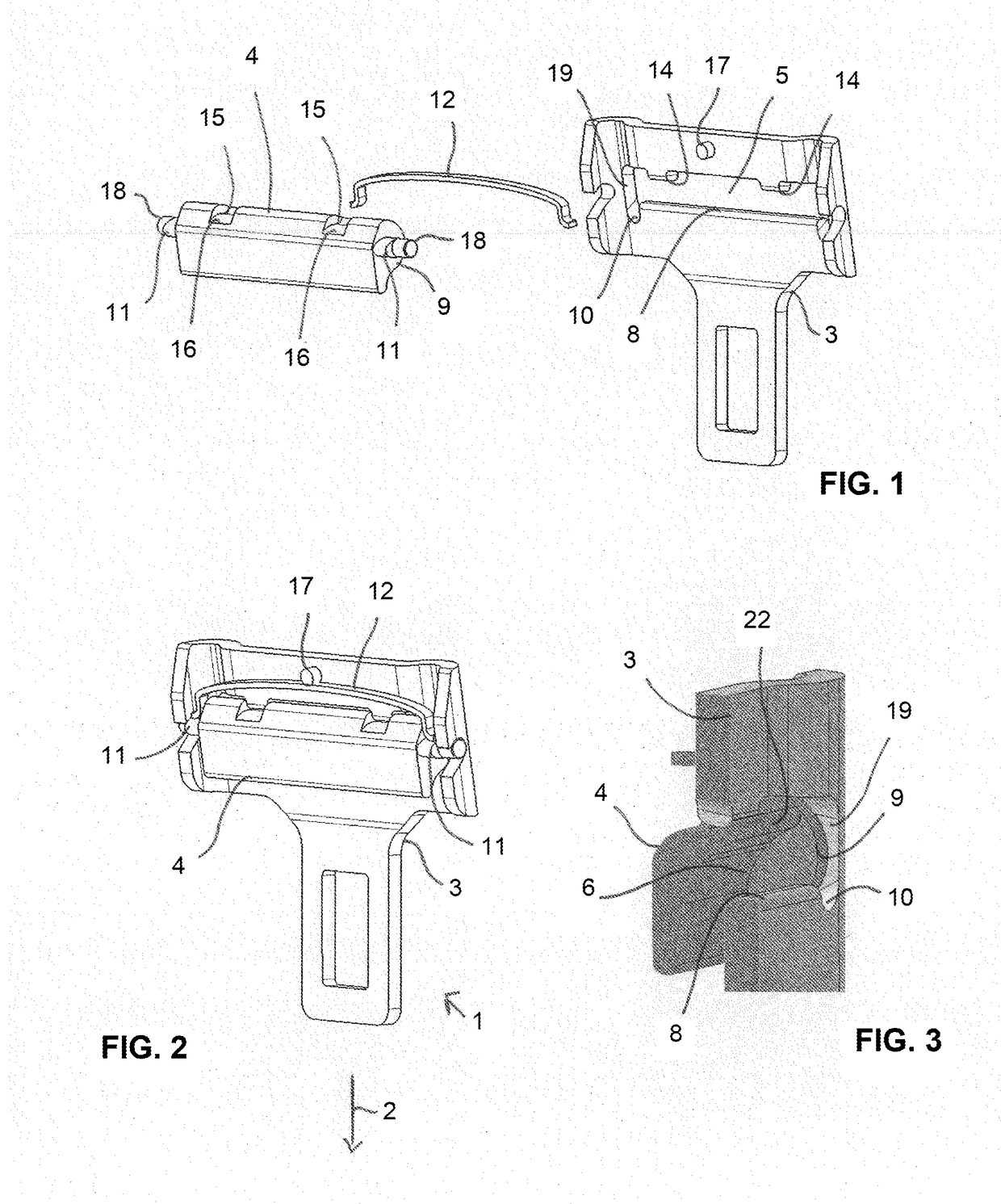
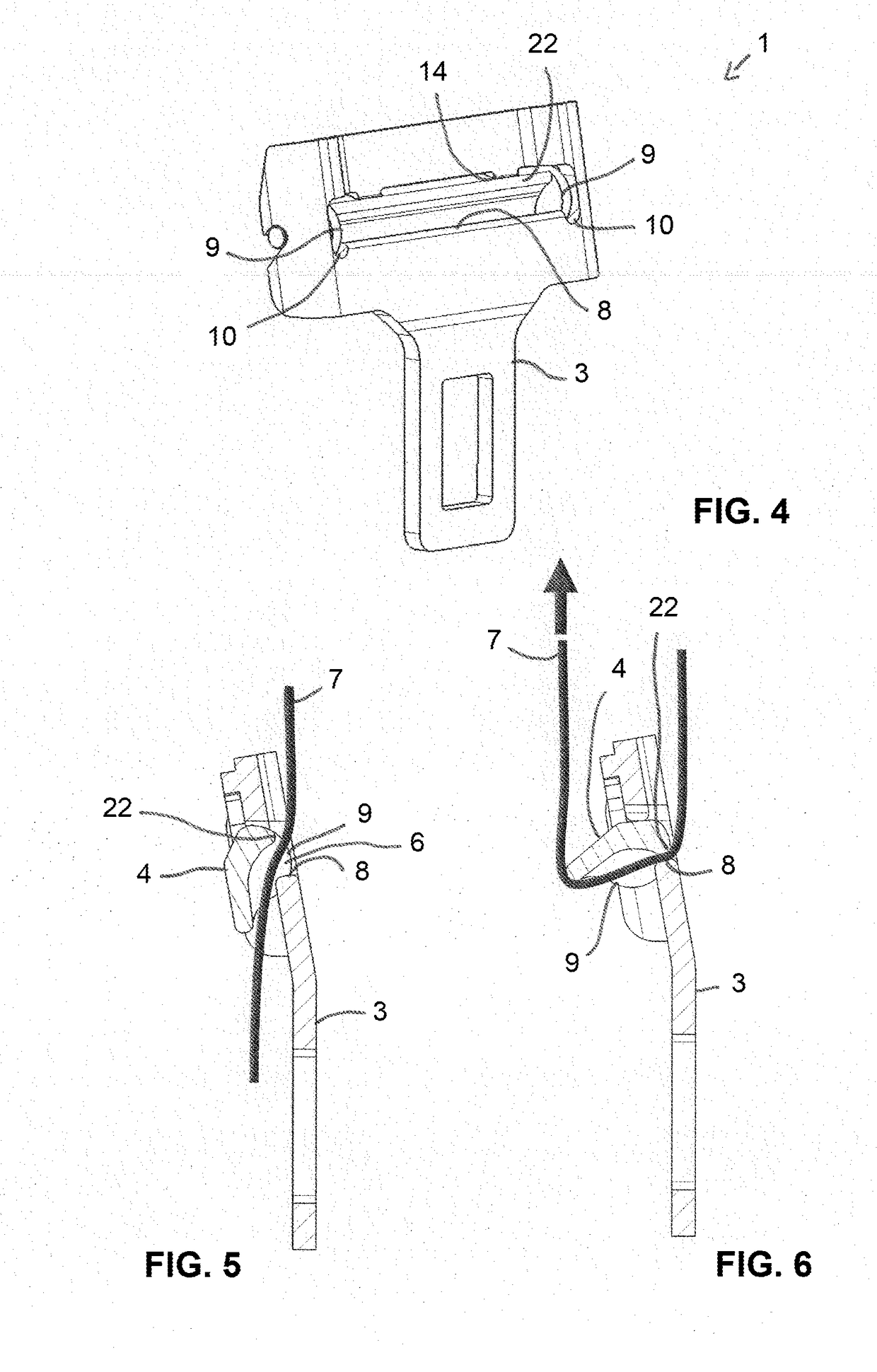
[0036]The first embodiment shown in FIGS. 1 to 4 of a belt tongue 1 includes a tongue body 3, which extends in an insertion direction 2. A cavity 5 is formed in the tongue body 3, which in the downward insertion direction 2 is bounded in sections by a clamping edge 8. Laterally to the clamping edge 8, the cavities 10 extend in the insertion direction 2. On the side of the cavity 5 lying opposite the clamping edge 8, there are lugs 14 configured on the tongue body 3 and projecting into the cavity 5. In addition, on the tongue body 3 there is a stop 17 configured, with which a leaf spring 12 is brought in contact with its middle region.

[0037]The belt tongue 1 further includes a clamping element 4 that is pivotably mounted with bearing pins 18 in the tongue body 3. Adjacent the bearing pins 18, a cam 11 is configured that tapers in one direction. In the installed state, the ends of the leaf springs 12 lie on the cam 11 so that torque is applied onto the clamping element 4.

[0038]The cla...

second embodiment

[0043] the clamping element 4 is pivotably mounted on the tongue body 3 by elastically deformable torsion element 13, wherein the torsion element 13 at the same time applies a reset force on the clamping element 4. The torsion element 13 for this purpose is non-rotatably secured by a form-fit on a first side 20 in a receptacle 28 on the tongue body 3. One the side 21 of the tongue body lying opposite the first side 20, torsion element 13 guided through the entire clamping element 4 is non-rotatably mounted in a receptacle 28 in the tongue body 3 as is clear from FIG. 11.

[0044]So that the torsion element 13 shown in FIG. 8 can be deformed (twisted) during a pivoting movement of the clamping element 4 over the greatest possible displacement, the torsion element 13 is only non-rotatably connected to the clamping element 4 on a side of the clamping element 4 assigned to the second side 21 of the tongue body 3 by a form-fit brought about by the receptacle 28, as is shown in FIG. 10. In t...


PUM


Abstract

A belt tongue having a tongue body, a clamping element in the tongue body, a belt webbing guided through a cavity in the tongue body and running through a gap between the clamping element and the tongue body. The belt webbing can be moved though the tongue body in an unstressed position and, in a stressed position is brought about by a tensile force on the belt webbing, is clamped on a clamping edge of the cavity by the clamping element that is pivotally mounted in the tongue. Laterally to the clamping element, guide sections are arranged, between which the belt webbing runs, so that the belt webbing in the lateral region of the cavity does not go between the clamping element and the tongue body. The cavity forms cavities laterally from the clamping edge.

Description

CROSS REFERENCE TO RELATED APPLICATIONS[0001]This application claims priority to German Patent Application No. 10 2014 114 207.1, filed on Sep. 30, 2014 and PCT / EP2015 / 072514, filed on Sep. 30, 2015.FIELD OF THE INVENTION[0002]The present invention relates to a belt tongue having a tongue body that extends in a belt webbing insertion direction, a clamping element being arranged in the tongue body such that a belt webbing guided through a cavity in the tongue body and running through a gap that is formed between the clamping element and the tongue body, can be moved though the tongue body in an unstressed free-running position. In a stressed position (upon a high level tension acting on the webbing) the clamping element brought about by a tensile force that is applied to the belt webbing, is clamped on a clamping edge of the cavity the clamping element that is pivotally mounted in the tongue body and can be pivoted into the cavity.BACKGROUND AND INTRODUCTORY DESCRIPTION OF THE INVENT...

Claims


Application Information

Patent Timeline
Patent Type & Authority Applications(United States)
IPC IPC(8): B60R22/185B60R22/18
CPCB60R2022/1812B60R22/1855A44B11/2557A44B11/2561
Inventor HERMANN, MICHELGRIKSCHAT, MARTINKRAMBECK, INGACORD, HANS-JORG
Owner AUTOLIV DEV AB
Learn More