

Motor control unit, failure detecting method, and electric power steering apparatus and vehicle equipped with the same
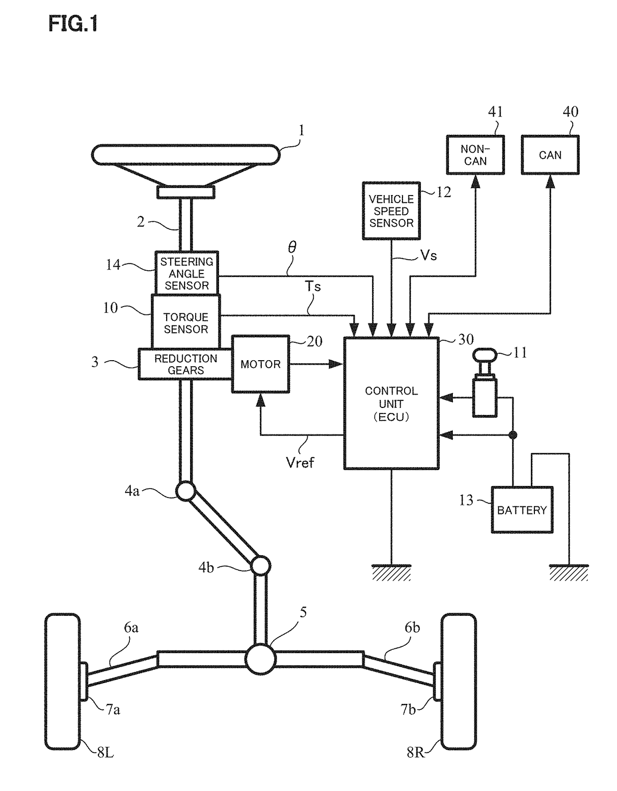
a technology of failure detection and motor control, which is applied in the direction of electrical steering, electronic commutators, transportation and packaging, etc., can solve the problems of not being able to provide and indispensable steering angle sensors b>14/b>, and achieve the effect of improving reliability and improving vehicle reliability
- Summary
- Abstract
- Description
- Claims
- Application Information
AI Technical Summary
Benefits of technology
Problems solved by technology
Method used
Image

Examples
first embodiment
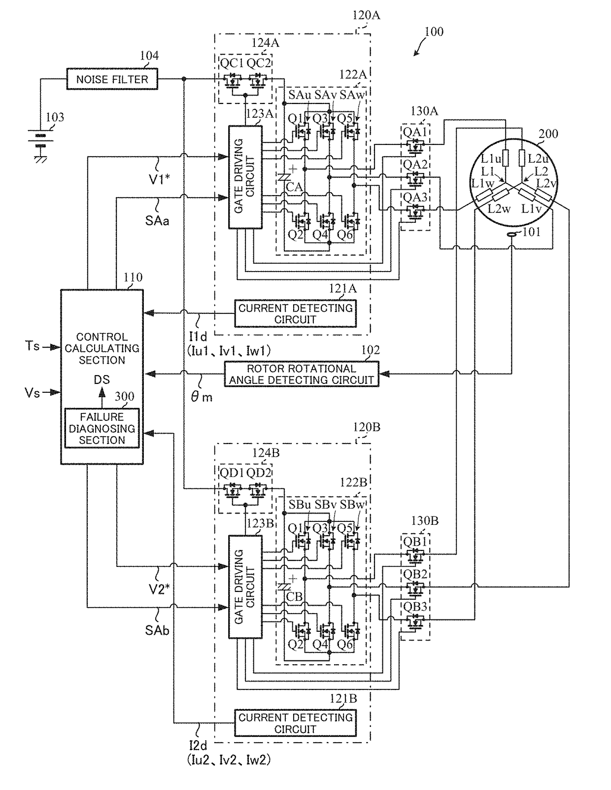
[0066]In such the motor control unit 100, the failure diagnosing section 300 in the control calculating section 110 has a configuration (the first embodiment) as shown in, for example, FIG. 7.
[0067]The phase currents Iu1, Iv1 and Iw1 of the first system windings L1 of the motor 200 which are detected by the current detecting circuit 121A are inputted into a three-phase / two-phase converting section 320, and the phase currents Iu2, Iv2 and Iw2 of the second system windings L2 of the motor 200 which are detected by the current detecting circuit 121B are inputted into a three-phase / two-phase converting section 330. Currents Iα1 and Iβ1 that are converted to two-phase currents of a α-β coordinate system at rest, which are orthogonal each other, at the three-phase / two-phase converting section 320 are adding-inputted into a current calculating section 321, and similarly currents Iα2 and Iβ2 that are converted to two-phase currents of the α-β coordinate system at rest, which are orthogonal ...
second embodiment
[0076]Although the adding-calculation of the two-phase currents is performed at the above current calculating sections 321 and 331, a subtracting-calculation of the two-phase currents may be performed (the second embodiment). However, the adding-calculation is basically better.
[0077]Next, another embodiment (the third embodiment) of the failure diagnosing section 300 will be described. In the third embodiment as shown in FIG. 10 corresponding to FIG. 7, current-calculations for the respective square-sums of the two-phase currents Iα1 and Iβ1 of the first system and those Iα2 and Iβ2of the second system are performed, as an alternative for the addition or the subtraction of the two phase currents Iα1 and Iβ1 of the first system and those Iα2 and Iβ2 of the second system.
[0078]That is, the two-phase currents Iα1 and Iβ1 of the first system are inputted into the current square-sum calculating section 322, and the square-sum current I12 (=Iα12+Iβ12) is calculated. Similarly, the two-pha...
fifth embodiment
[0084]Although the square-sum of the three-phase currents is calculated in the fifth embodiment, it may be the square-sum of currents (arbitrary two phases) for at least two-phase or more.
PUM
 Abstract
Description
Claims
Application Information