Propulsion engine for an aircraft

a technology for propelling engines and aircraft, applied in the direction of efficient propulsion technologies, machines/engines, power plant types, etc., can solve the problems of turbofan jet engines experiencing efficiency loss minimizing or negating, drag on aircraft, and effect on the net propulsive thrust of aircra

Active Publication Date: 2017-10-19
GENERAL ELECTRIC CO
View PDF9 Cites 46 Cited by
  • Summary
  • Abstract
  • Description
  • Claims
  • Application Information

AI Technical Summary

Benefits of technology

[0006]Aspects and advantages of the invention will be set forth in part in the following description, or may be obvious from the description, or may be learned through practice of the invention.

Problems solved by technology

However, a drag on the aircraft including the turbofan jet engines, also has an effect on the net propulsive thrust of the aircraft.
As a result, such turbofan jet engines can experience an efficiency loss minimizing or negating any benefits of reduced drag on the aircraft.

Method used


Image

  • Propulsion engine for an aircraft
  • Propulsion engine for an aircraft
  • Propulsion engine for an aircraft

Examples


Embodiment Construction

[0017]Reference will now be made in detail to present embodiments of the invention, one or more examples of which are illustrated in the accompanying drawings. The detailed description uses numerical and letter designations to refer to features in the drawings. Like or similar designations in the drawings and description have been used to refer to like or similar parts of the invention.

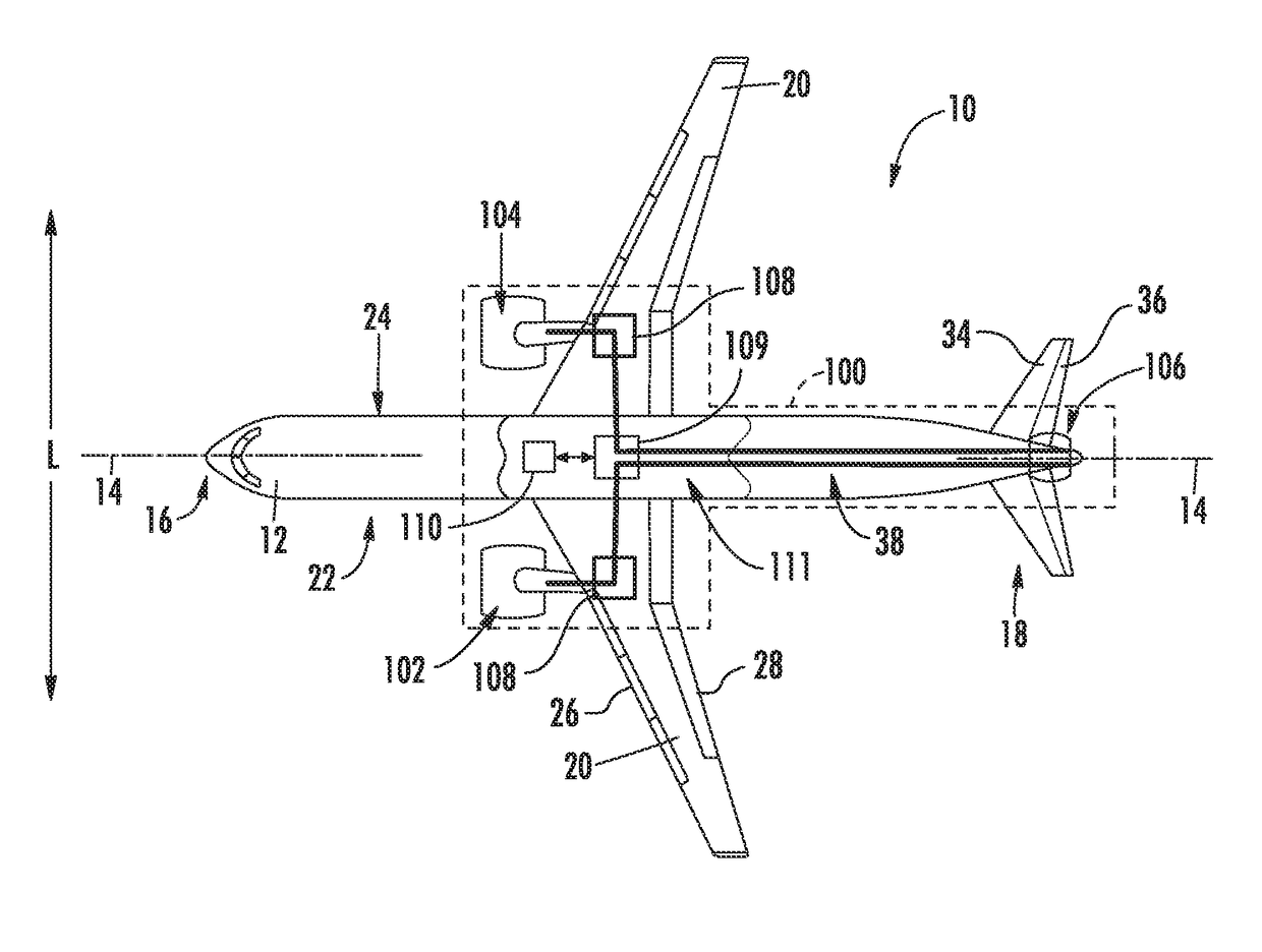
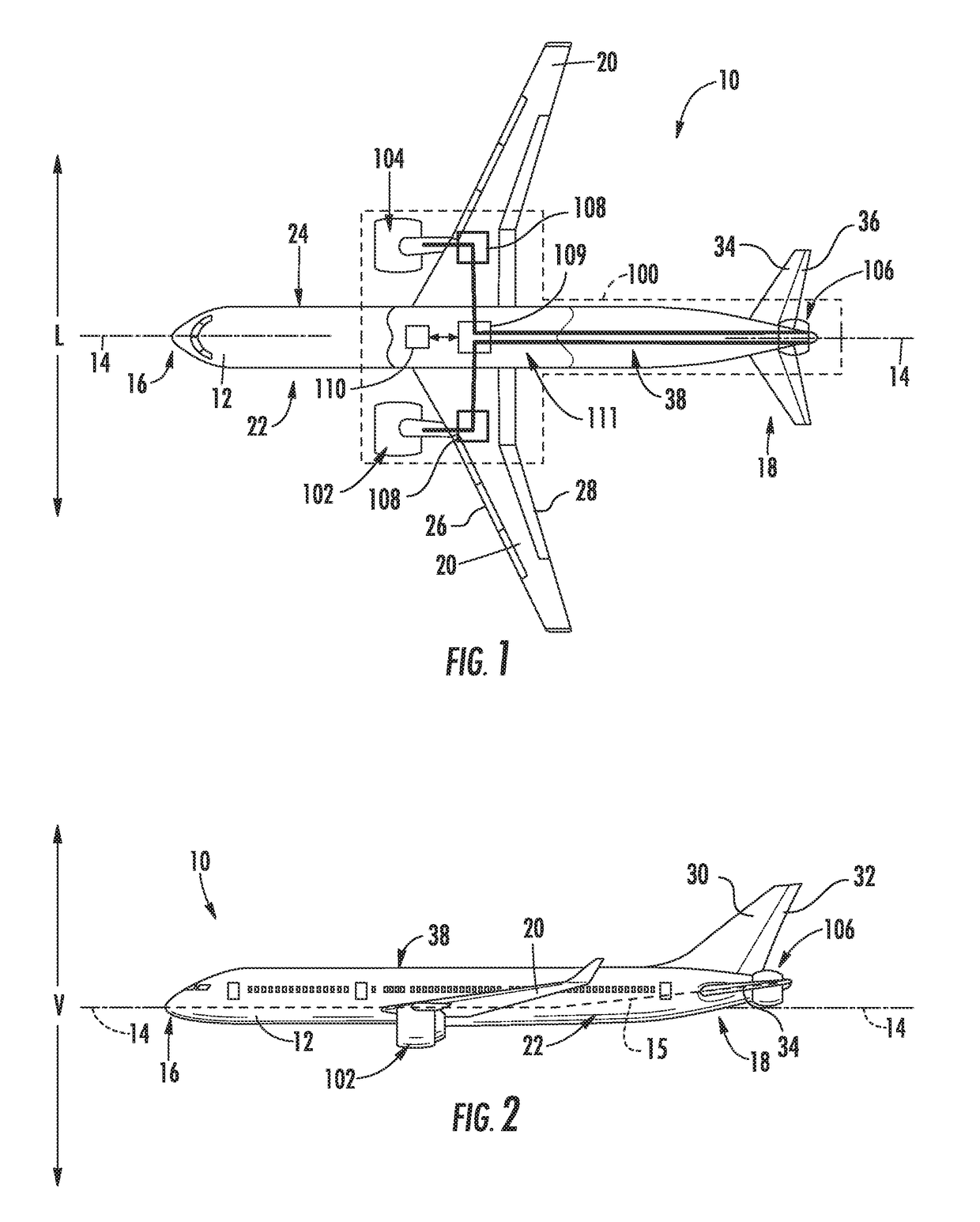
[0018]As used herein, the terms “first”, “second”, and “third” may be used interchangeably to distinguish one component from another and are not intended to signify location or importance of the individual components. The terms “forward” and “aft” refer to the relative positions of a component based on an actual or anticipated direction of travel. For example, “forward” may refer to a front of an aircraft based on an anticipated direction of travel of the aircraft, and “aft” may refer to a back of the aircraft based on an anticipated direction of travel of the aircraft. The terms “upstream” and “downs...


PUM


Abstract

A propulsion system for an aircraft is provided having a propulsion engine configured to be mounted to the aircraft. The propulsion engine includes an electric machine defining an electric machine tip speed during operation. The propulsion system additionally includes a fan rotatable about a central axis of the electric propulsion engine with the electric machine. The fan defines a fan pressure ratio, RFP, and includes a plurality of fan blades, each fan blade defining a fan blade tip speed. The electric propulsion engine defines a ratio of the fan blade tip speed to electric machine tip speed that is within twenty percent of the equation, 1.68×RFP−0.518, such that the propulsion engine may operate at a desired efficiency.

Description

FIELD OF THE INVENTION[0001]The present subject matter relates generally to an aircraft propulsion system including an electric propulsion engine.BACKGROUND OF THE INVENTION[0002]A conventional commercial aircraft generally includes a fuselage, a pair of wings, and a propulsion system that provides thrust. The propulsion system typically includes at least two aircraft engines, such as turbofan jet engines. Each turbofan jet engine is mounted to a respective one of the wings of the aircraft, such as in a suspended position beneath the wing, separated from the wing and fuselage. Such a configuration allows for the turbofan jet engines to interact with separate, freestream airflows that are not impacted by the wings and / or fuselage. This configuration can reduce an amount of turbulence within the air entering an inlet of each respective turbofan jet engine, which has a positive effect on a net propulsive thrust of the aircraft.[0003]However, a drag on the aircraft including the turbofa...

Claims


Application Information

Patent Timeline
Patent Type & Authority Applications(United States)
IPC IPC(8): B64D27/24B64D27/18B64D27/02F02C7/36F02C7/20F02C3/04
CPCB64D27/24B64D27/02B64D27/18F02C3/04B64D2027/026F02C7/36Y10S903/906Y10S903/907Y10S903/905F02C7/20B64D35/02F02K3/04F05D2220/76Y02T50/10Y02T50/60
Inventor NIERGARTH, DANIEL ALANVONDRELL, RANDY M.MILLER, BRANDON WAYNEMARRINAN, PATRICK MICHAEL
Owner GENERAL ELECTRIC CO
Why Eureka
Try Eureka