Spring box of cordless window covering and friction mechanism of the same

a cordless window covering and friction mechanism technology, applied in the field of window coverings, can solve the problems of blankets not being able to be completely raised, blankets are heavy, and the bottom rail tends to rebound, and achieve the effect of high friction

Inactive Publication Date: 2017-10-19
NIEN MADE ENTERPRISE CO LTD
View PDF2 Cites 19 Cited by
  • Summary
  • Abstract
  • Description
  • Claims
  • Application Information

AI Technical Summary

Benefits of technology

[0015]In an embodiment, the friction member comprises a pushing block and at least one elastic member. The pushing block is detachably engaged with the movable member, and has the effect portion. The at least one elastic member is provided between the pushing block and the movable member, and is deformable by compression.
[0016]In an embodiment, the movable member has an engaging portion. The at least one effect portion of the friction member comprises two effect portions, wherein one of the effect portions is engaged with the engaging portion, while the other one of the effect portions abuts against the wall of the post.
[0017]The present invention further provides a resistance structure, including a base, a post rotatably connected to the base, a bolt movable by the post, a movable member having a threaded hole being passed through by the bolt, a restricting member provided on the

Problems solved by technology

However, when the blanket is just fully expanded, the bottom rail tends to rebound due to the effect of the stretchable tubes.
On the other hand, the blanket may not be able to be completely raised even if user intends to do so, for the blanket would exert a downward pushing force on the b

Method used


Image

  • Spring box of cordless window covering and friction mechanism of the same
  • Spring box of cordless window covering and friction mechanism of the same
  • Spring box of cordless window covering and friction mechanism of the same

Examples


first embodiment

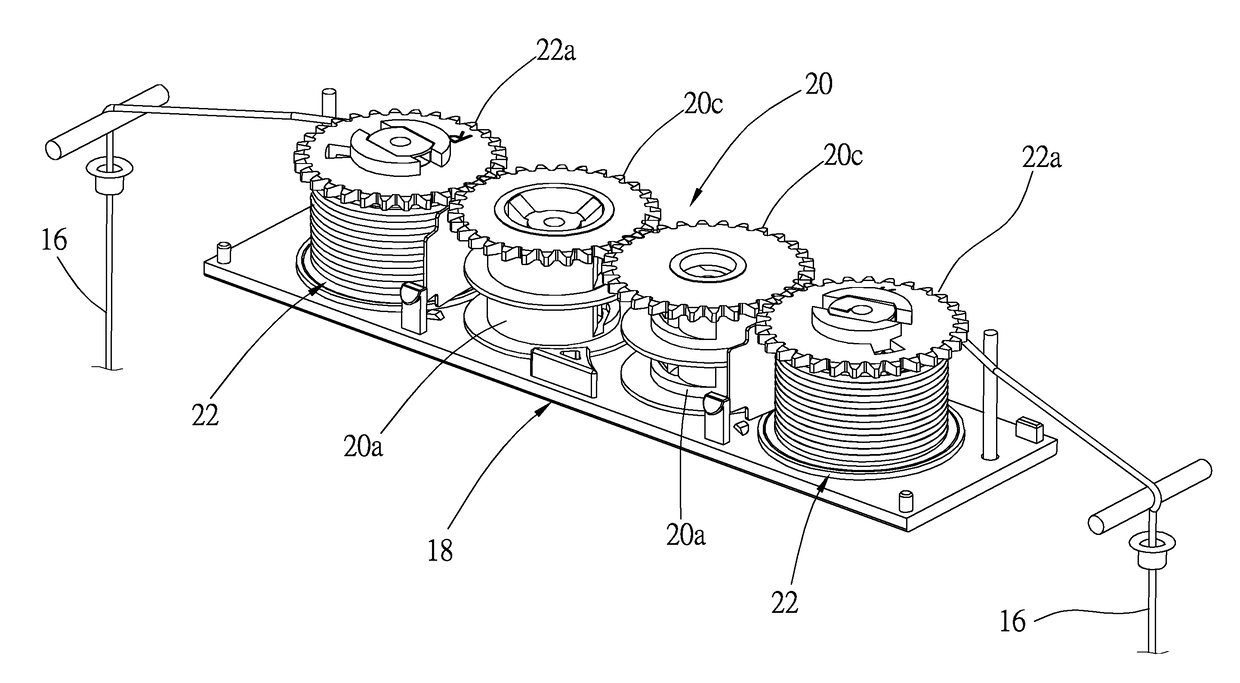
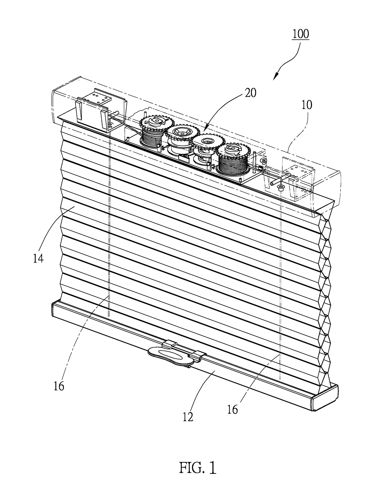
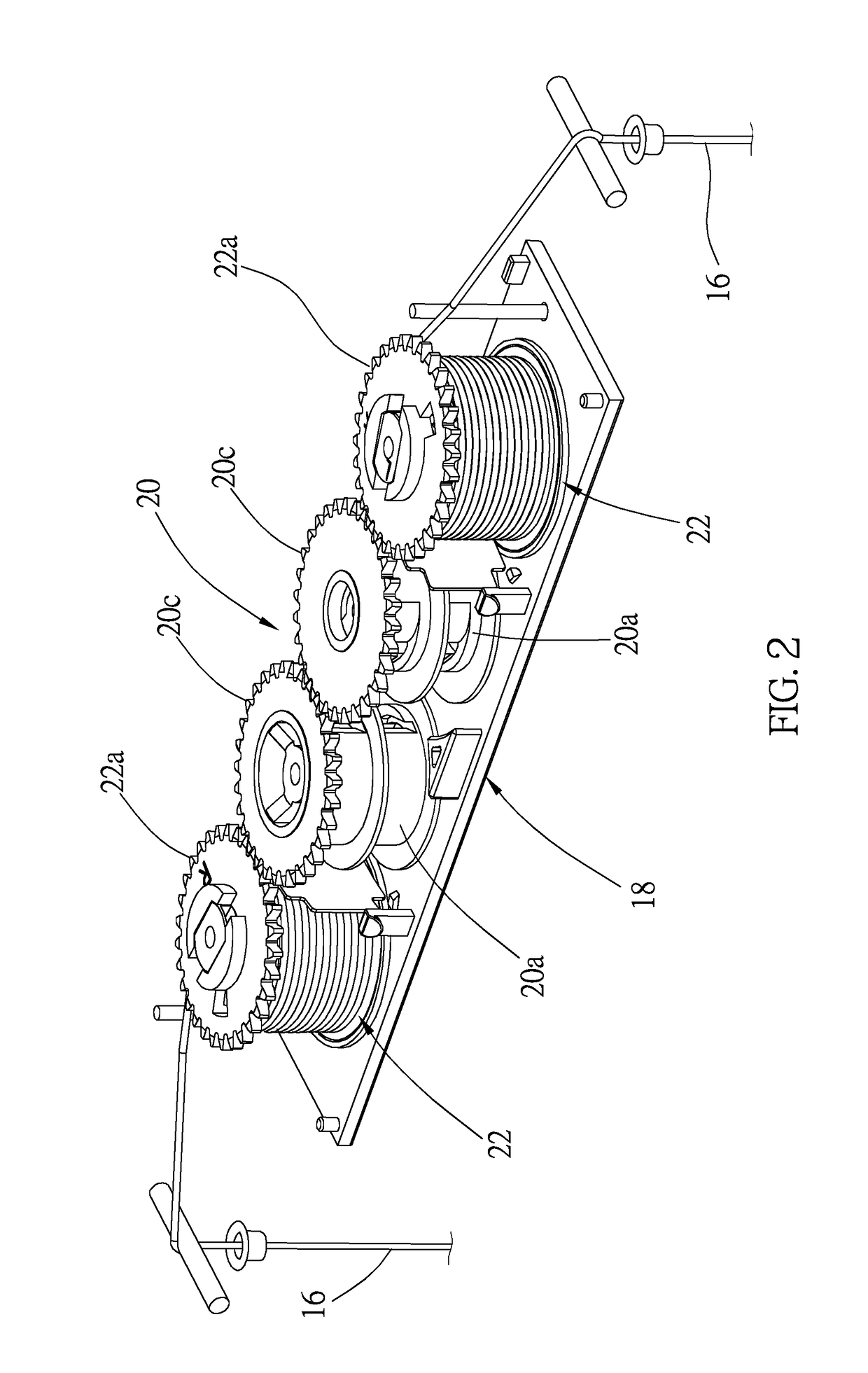
[0040]As mentioned above, the bottom rail 12 of the cordless window covering 100 could stay at a predetermined position through the pulling force provided by the torsion springs of the prestressing device 20. However, to ensure that the bottom rail 12 simply stays at the right position, the spring box of the first embodiment is further provided with a resistance structure to help the bottom rail 12 to stay at the predetermined position as expected.

[0041]As shown in FIG. 3, the resistance structure of the spring box includes two round holes 18a, which are provided on a surface of the base 18, and a plurality of restricting members 18b, wherein each of the restricting members 18b is integrally formed to surround one of the round holes 18a, and is vertically connected to the surface of the base 18. Furthermore, a non-circular hole 22b is provided on a top plate (i.e., the gear 22a) of each of the posts 22. The resistance structure further includes two guiding members, two movable membe...

third embodiment

[0059]When the bottom rail 12 is pulled downward to release the lifting cords 16, the post 36 and the guiding member 38 are indirectly moved to rotate. As shown in FIG. 16, since the movable member 40 abuts against the restricting wall 32a, the movable member 40 is not rotatable, and only movable along the bolt 38a. In the third embodiment, while the bottom rail 12 is being pulled downward, the upward moving distance of the movable member 40 remains within the straight segment 36b until the bottom rail 12 reaches half way to fully expand the window covering. In other words, when the bottom rail 12 is lowered to about half way to fully expand the window covering, the pushing block 42a starts to abut against a bottom edge of the tapered segment 36a. When the bottom rail 12 is further pulled downward, and before the bottom rail 12 reaches the lowest position, the pushing block 42a shifts toward the movable member 40 due to the restriction of the tapered segment 36a, and pushes the elas...


PUM


Abstract

A spring box provided in one headrail of a window covering is disclosed, including a base, a post rotatably provided on the base to wind up a lifting cord, and a prestressing device which provides a pulling force to the post to rotate it in a predetermined direction. The spring box further includes a guiding member provided in the post to be rotated by the post, a movable member which moves along the guiding member in a non-rotating manner when the guiding member is rotated, and a friction member which is compressed and deformed to increase a friction between it and an inner wall of the post when the movable member is moved in a predetermined direction, providing a resistance effect to the rotation of the post, which makes one bottom rail of the window covering stay at a predetermined position.

Description

BACKGROUND OF THE INVENTION1. Technical Field[0001]The present invention relates generally to a window covering, and more particularly to a spring box of a cordless window covering and a friction mechanism thereof.2. Description of Related Art[0002]A conventional cordless window covering usually uses an automatic reeling device, e.g., a spring box, to move the bottom rail relative to the headrail, so as to expand or raise the shield structure of the window covering.[0003]Such shield structure is typically made of a continuous material, and the common types include cellular shade and pleated shade, which are both stretchable. Take a cellular shade as an example, the blanket has multiple horizontal tubes, which allow the blanket to be expanded or raised vertically. The stacked blanket would have a compact size. With these stretchable tubes, the blanket has abundant flexibility to be expanded or raised. However, when the blanket is just fully expanded, the bottom rail tends to rebound ...

Claims


Application Information

Patent Timeline
IPC IPC(8): E06B9/322F03G1/00E06B9/262
CPCE06B9/322E06B9/262E06B2009/2627E06B2009/3222F03G1/00
Inventor CHEN, LINNIEN, KENG-HAO
Owner NIEN MADE ENTERPRISE CO LTD
Why Eureka
Try Eureka