Automatic Re-Loading Air-Sampling and Pneumatic Transport System

Active Publication Date: 2017-10-19
DAVID BRIAN J
View PDF0 Cites 2 Cited by
  • Summary
  • Abstract
  • Description
  • Claims
  • Application Information

AI Technical Summary

Benefits of technology

[0017]Embodiments of the invention can form a substantially airtight inlet seal among the vacuum pump, inlet tube, and chamber at the sampling position by using a first pair of spring-loaded, double-lipped cups biased against opposite faces of the wheel assembly. Sim

Problems solved by technology

The utility of air-sampling devices that can analyze samples autonomously is often constrained by costly and delicate instrumentation needed for specialized analysis of the air samples.
GC-MS machines cost up to several hundred thousand dollars and may not be cost effective given the limited scope of analysis in the field.
Furthermore, such a combination would require extensive calibration by a qualified technician prior to each use, to ensure accurate analysis, as transport alone could cause significant analytical variation in the results.
A known example of such a system is the microfluidic bio-agent autonomous networked detector (“M-BAND”) produced by PositiveID Corporation, which was at first considered for use in the Department of Homeland Security's BioWatch program, but was recently abandoned due to high costs, frequent false positive results, and frequently required maintenance.
Despi

Method used


Image

  • Automatic Re-Loading Air-Sampling and Pneumatic Transport System
  • Automatic Re-Loading Air-Sampling and Pneumatic Transport System
  • Automatic Re-Loading Air-Sampling and Pneumatic Transport System

Examples


Embodiment Construction

[0034]Embodiments of the present invention now may be described more fully hereinafter with reference to the accompanying drawings, in which some, but not all, embodiments of the invention are shown. Indeed, the invention may be embodied in many different forms and should not be construed as limited to the embodiments set forth herein. Like numbers refer to like elements throughout.

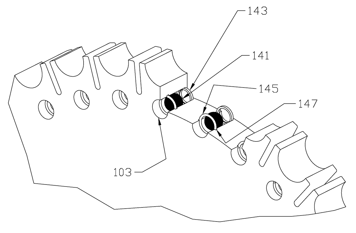
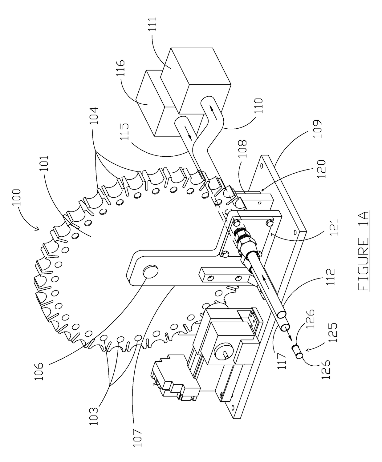
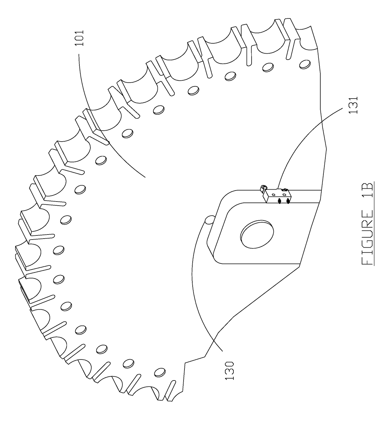
[0035]FIG. 1A is a perspective view of one embodiment of an automatic re-loading air-sampling and pneumatic transport system constructed in accordance with the teachings of the present invention with a view of a front face of a wheel assembly. In FIG. 1A, an embodiment of automatic re-loading air-sampling and pneumatic transport system 100 comprises a wheel assembly 101 and contains a plurality of chambers 103 comprising transverse cylindrical spaces with differently sized openings on opposite faces of the wheel assembly. For example, wheel assembly 101 may comprise thirty-two chambers 103, each having a ...


PUM


Abstract

Embodiments of the invention collect solid, vapor, and/or biological components of the air in air-sampling cartridges that are then transported to an off-site location by pneumatic pressure. Operation proceeds by first collecting a sample of air in an air-sampling cartridge in a sampling position, then advancing a cartridge assembly to move the now-used sampling cartridge into a transport position while simultaneously moving an unused sampling cartridge into the sampling position, and finally using pneumatic pressure to push the used sampling cartridge in the transport position to an off-site location via a transport tube. The sampling operation can begin again while the transport operation is in still in progress. These operations can be pre-programmed locally or triggered by remote communication. Continued operation is possible due to a plurality of unused air-sampling cartridges retained in the cartridge assembly. Since operations can be triggered remotely and air samples are autonomously transported off site, embodiments of this invention eliminate unnecessary risks to human health created by other air-sampling devices, which require an operator to be present at a potentially hazardous sampling site to activate the device or retrieve air samples. Additionally, embodiments of the invention can be installed preemptively to eliminate risks to human health created when an operator must deliver a portable air-sampling device to a potentially contaminated sampling site. Furthermore, embodiments of the invention allow rapid retrieval of air samples following sample collection, which can expedite analysis and identification of aerosols and consequently help minimize human exposure to potentially dangerous and life-threatening chemical and biological contaminants.

Description

CROSS REFERENCE TO RELATED APPLICATIONS[0001]This application is a continuation-in-part of U.S. patent application Ser. No. 15 / 098,405, filed Apr. 14, 2016, which is a continuation of U.S. patent application Ser. No. 14 / 466,132, now U.S. Pat. No. 9,341,547, filed Aug. 22, 2014, which claims priority under 35 U.S.C. §119(e) to U.S. Provisional Patent Application Ser. No. 61 / 959,659, filed Aug. 29, 2013, all of which are hereby incorporated by reference.BACKGROUND[0002]The present invention is related to the field of air sampling. More particularly, the present invention is related to systems that automatically collect samples of air and transport those samples away from the sampling site during continued and uninterrupted operation.DESCRIPTION OF RELATED ART[0003]Systems that sample air for aerosols, including suspensions of solid or liquid particles, have been used in a wide range of applications. For example, systems have been used to sample and analyze vehicle exhaust to ensure co...

Claims


Application Information

Patent Timeline
IPC IPC(8): G01N1/24G01N1/22G01N33/00G01N1/18
CPCG01N1/2205G01N2001/2223G01N2001/185G01N1/2273G01N1/24G01N33/0036G01N2035/0481
Inventor DAVID, BRIAN J.
Owner DAVID BRIAN J
Why Eureka
Try Eureka