Object tracking device and method

a tracking device and object technology, applied in the field of computer vision, can solve the problems of low auto-focus accuracy and blurred images, and achieve the effects of high accuracy, accurate indication of tracking object areas, and stable tracking

Inactive Publication Date: 2017-10-19
SONY CORP
View PDF1 Cites 24 Cited by
  • Summary
  • Abstract
  • Description
  • Claims
  • Application Information

AI Technical Summary

Benefits of technology

[0025]According to the embodiments of the present invention, by generating the binary map and the boundary rectangle of the target object area, an auto-focus module is prevented from focusing on a background area inside the output rectangle, and a tracked object partially overlapped with an obstacle whose color is similar or the same with that of the tracked object can be stably tracked. If the tracking method is used in the autofocus function of a camera, the camera can focus on a correct tracked object even if the tracked object is partially overlapped with the obstacle whose color is similar or the same with that of the tracked object. The method provided by the present invention can track any to-be-tracked object selected by a user through a camera's graphical user interface (GUI), and can generate the object binary map which can accurately indicate a tracking object area. By using the object binary map, the camera can keep focusing on the tracking object area with high accuracy.

Problems solved by technology

For example, if the target tracking technology is used in an auto-focus function, wrong tracking results may cause blurred images shot because focused regions in the shot images may be wrong obstacles.
But for the auto-focus function of a camera, this rectangle may cause a low auto-focus accuracy problem.

Method used


Image

  • Object tracking device and method
  • Object tracking device and method
  • Object tracking device and method

Examples


first embodiment

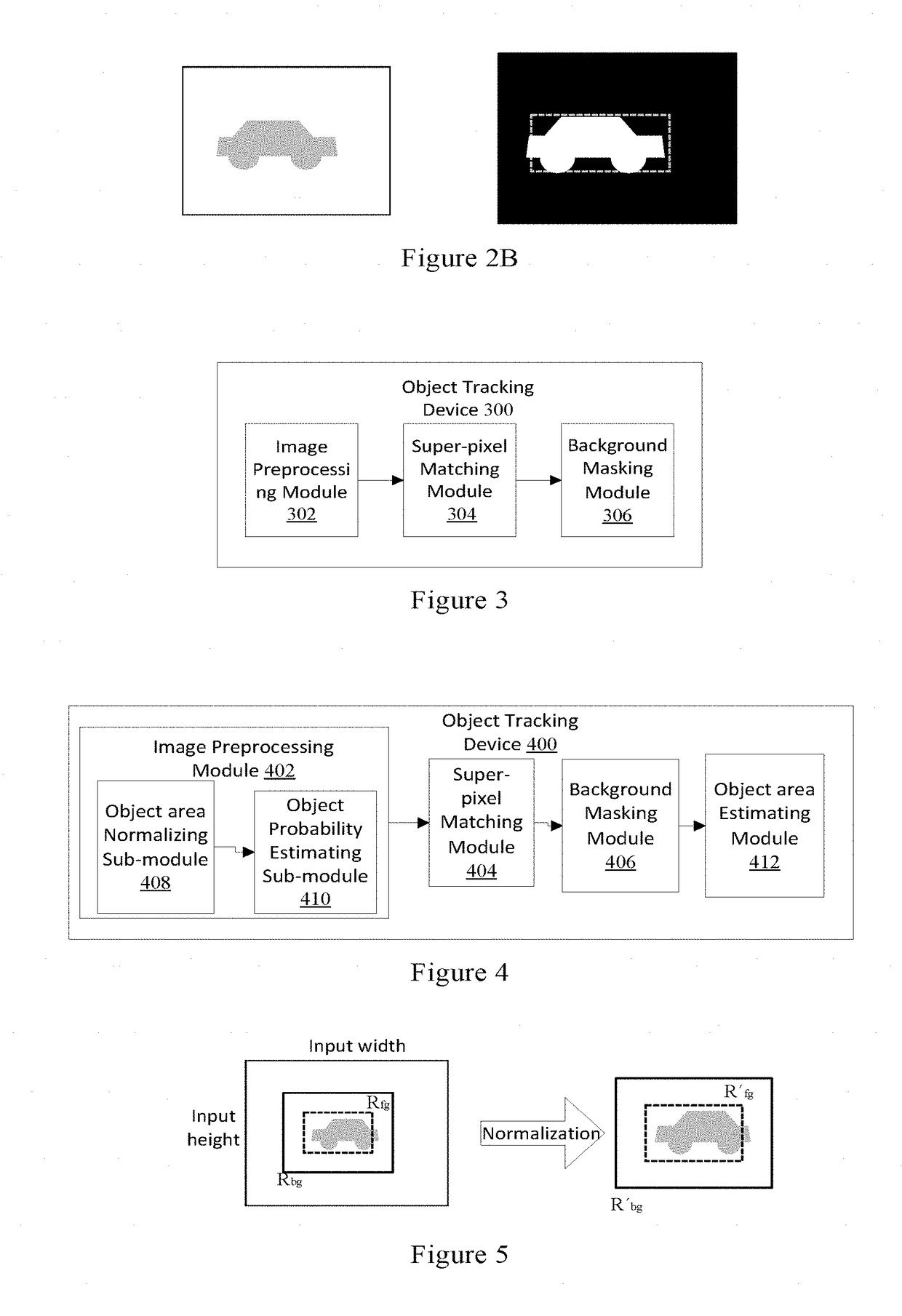
[0051]FIG. 3 is a block diagram of an object tracking device according to the present invention. Referring to FIG. 3, the object tracking device 300 comprises a processor and a memory (not shown in the FIG. 3). The processor comprises an image preprocessing module 302 configured to normalize a background area of an input image to obtain a normalized image with a fixed-size background area, a super-pixel matching module 304 configured to convert the normalized image into a super-pixel image by use of a super-pixel algorithm and match the super-pixel image with a reference super-pixel area to find a matching area which has highly similar super-pixel colors with the reference super-pixel area from the super-pixel image, and a background masking module 306 configured to mask the super-pixel image with the matching area to obtain a super-pixel masked image whose background area outside the matching area is masked.

[0052]The object tracking device according to the first embodiment of the p...

second embodiment

[0053]FIG. 4 is a block diagram of an object tracking device according to the present invention. Referring to FIG. 4, the object tracking device 400 comprises a processor and a memory (not shown in the FIG. 4). The processor comprises an image preprocessing module 402, a super-pixel matching module 404, a background masking module 406, and an object area estimation module 412, wherein the image preprocessing module 402 comprises an object area normalizing sub-module 408 and an object probability estimating sub-module 410. These modules will be described in detail hereinafter.

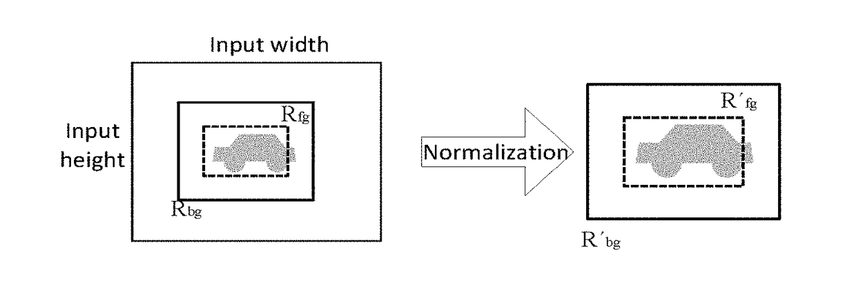
[0054]The object area normalizing sub-module 408 is configured to normalize a background area of an input image to obtain a normalized image with a fixed-size background area. Particularly, the object area normalizing sub-module 408 is configured to scale the background area of the input image to a fixed size via a length-width ratio the same as that of the background area of the input image to obtain the normal...


PUM


Abstract

An object tracking device and method and image shooting apparatus are provided. The object tracking device includes a processor and a memory, wherein the processor includes an image preprocessing module; a super-pixel matching module; and a background masking module configured to mask a super-pixel image having a matching area, in order to obtain a super-pixel masked image whose background area outside of the matching area is masked. The present invention is able to eliminate obstacles from a output area by a way of background masking, accurately and stably tracking the object.

Description

TECHNICAL FIELD[0001]The present invention is related to the field of computer vision, and more particularly to an object tracking device and method.BACKGROUND ART[0002]Target tracking technology is used for auto-focus, auto white balance and auto-exposure to shoot desired images and videos via camera devices. However, referring to FIG. 1A, conventional target tracking methods in which a tracking output rectangle 102, (namely, a tracking output area or a tracking output block) is fitted to the size and the shape of a tracked target A are likely to wrongly track a similar or the same target obstacle B especially when the tracked target A and the obstacle Bare partially overlapped, that is, when both the tracked target A and the obstacle B appear in the tracking output rectangle. For example, if the target tracking technology is used in an auto-focus function, wrong tracking results may cause blurred images shot because focused regions in the shot images may be wrong obstacles.[0003]O...

Claims


Application Information

Patent Timeline
Patent Type & Authority Applications(United States)
IPC IPC(8): G06K9/62H04N5/232G06T7/194H04N5/225H04N9/73H04N5/235
CPCG06K9/6215G06T7/194H04N5/2257H04N5/2351H04N9/735H04N5/23212G06T2207/20048G06T2207/10024H04N23/67H04N5/2226G06T2207/20072G06T2207/20076G06T7/215G06T7/248G06T7/277H04N23/675H04N23/71G06F18/22H04N23/57H04N23/88
Inventor SATO, YOICHIRO
Owner SONY CORP
Why Eureka
Try Eureka