Method for transmitting video surveillance images

a video surveillance and image technology, applied in the field of video, can solve the problems of low quality images decoded from video frames received in real time that are not distinctly visible, consume a large quantity of telecommunications network bandwidth, and are difficult to distinguish, so as to enhance the quality of images, increase the quantity of information, and enhance the quality of a series

Active Publication Date: 2017-10-19
AIRBUS DS
View PDF6 Cites 2 Cited by
  • Summary
  • Abstract
  • Description
  • Claims
  • Application Information

AI Technical Summary

Benefits of technology

[0025]Still preferably, coding the series of images acquired is made into a series of base video frames and into a plurality of series of enhancement video frames in order to enhance the quality of the images.
[0026]In this case, the series of enhancement video frames are hierarchized, each series of enhancement video frames comprising a further quantity of information making it possible to enhance the quality of a series of images decoded from said series of base video frames and the series of enhancement video frames with a lower hierarchical level,
[0027]Thus, the first series of enhancement video frames is added to the series of base video frames and then each series with an immediately upper level is added to the series with an immediately lower level. In practice, the vide...

Problems solved by technology

Low quality images decoded from video frames received in real time generally do not make it possible to distinctly view the details of an image enabling, for example, a person's face to be identified, which can be a major drawback, in particular upon obtaining evidence within the context of a trial or lawsuit.
Conversely, the video frames coded in the second coding format are not transmitted in real time to the control room, because this would consume a too high quantity of bandwidth of the telecommunications network.
There is a problem when an operator of the control room, who has detected an event in the images decoded from low quality video frames received in real time, wants to retrieve said event in the images decoded...

Method used


Image

  • Method for transmitting video surveillance images
  • Method for transmitting video surveillance images
  • Method for transmitting video surveillance images

Examples


Embodiment Construction

[0063]Description of one embodiment of the system according to the invention

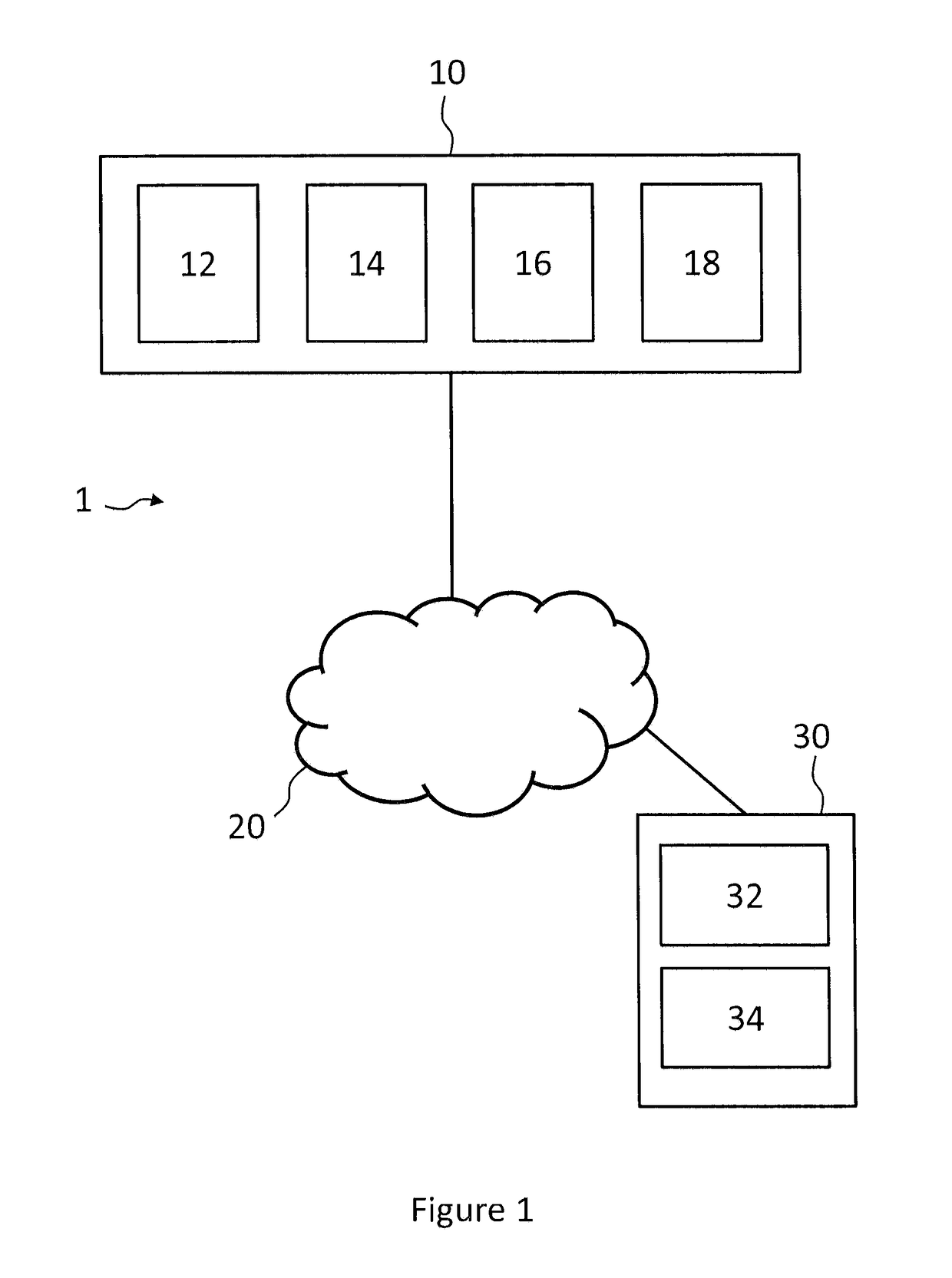
[0064]FIG. 1 schematically represents one embodiment of the system 1 according to the invention.

I. System 1

[0065]In this example, the system 1 comprises a surveillance device 10, a telecommunications network 20 and a control room 30.

a) Surveillance Device 10

[0066]The surveillance device 10 is preferably mounted in a vehicle, especially an automotive vehicle. It can however be in the form of a fixed station, for example mounted to a pole or to a wall.

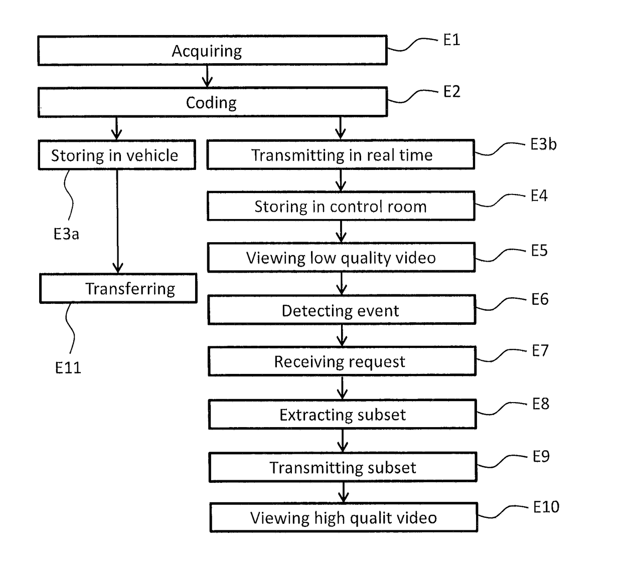
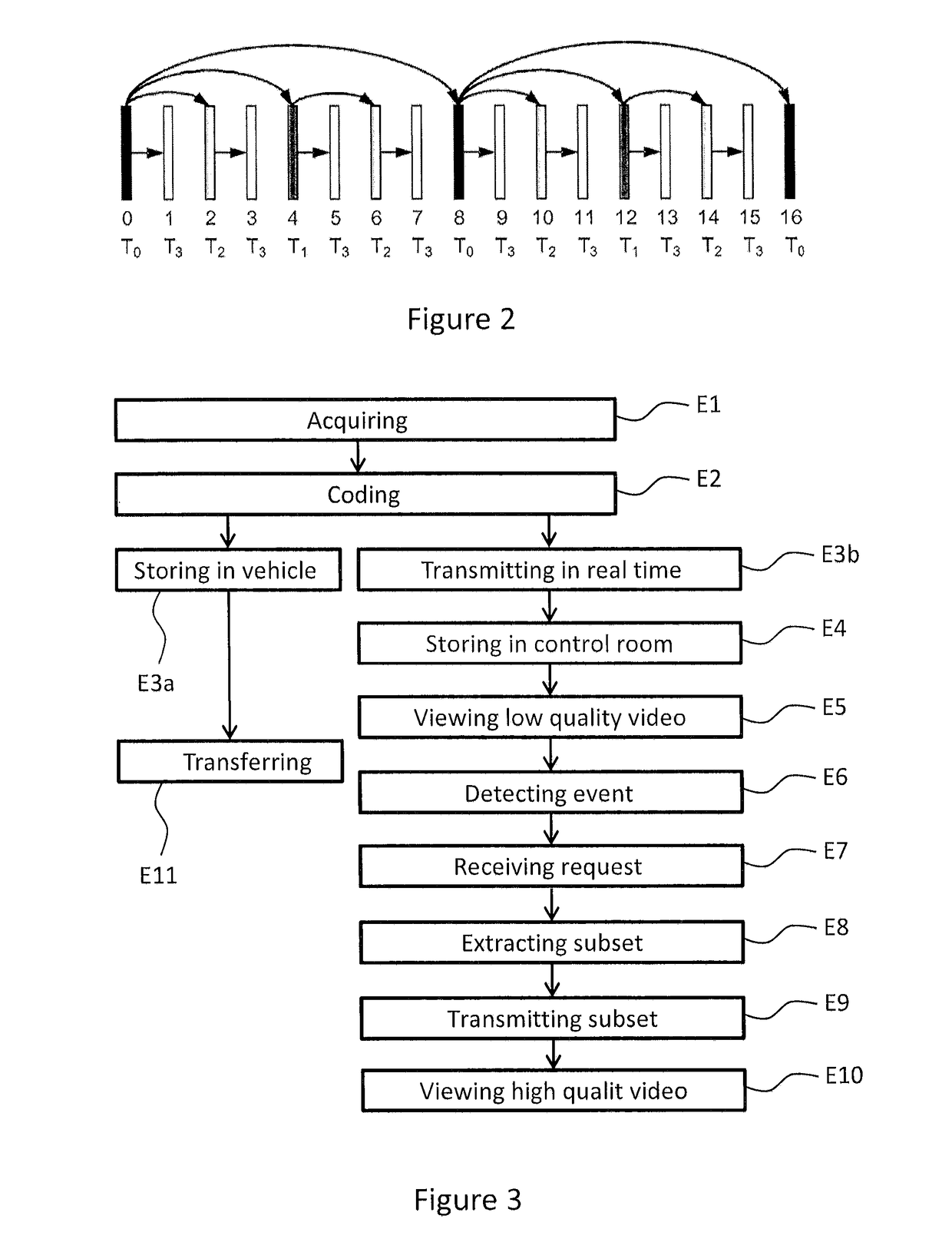
[0067]For an operator of the control room 30 to be able to view images of the environment of the surveillance device 10, the surveillance device 10 comprises, as illustrated in FIG. 1, an acquiring unit 12, a coding unit 14, a transmitting unit 16 and a storage unit 18.

[0068]The acquiring unit 12 is configured to acquire a series of images of the environment of the surveillance device 10. For example, the acquiring unit 12 can comprise one or more video cameras o...


PUM


Abstract

A method of transmission by a surveillance device to a control room, via a telecommunications network, of a series of images, includes steps, implemented by the surveillance device, of acquisition of a series of images, of coding of the series of images acquired into a series of base video frames including a first quantity of information and into at least one series of enhancement video frames of the series of base video frames, the series of enhancement video frames including a second quantity of information making it possible to enhance the quality of the series of images coded into the series of base video frames, of transmission in real time via the telecommunications network of at least the series of base video frames to the control room, and of storage of at least the series of enhancement video frames.

Description

TECHNICAL FIELD AND OBJECT OF THE INVENTION[0001]The present invention relates to the field of video and relates more particularly to a method, a device and a system for transmitting video surveillance images.[0002]The invention in particular finds application in the field of remote analysis of images acquired by one or more cameras, for example onboard a vehicle.STATE OF THE ART[0003]Video surveillance systems are used in a known manner for security purposes, in particular in public spaces. The cameras of these systems, which can be fixed or onboard vehicles, are connected, via a telecommunications network, to a control room in which an operator views the images.[0004]In existing onboard solutions, the surveillance device is mounted in an automotive vehicle and comprises an image acquiring unit comprising one or more video cameras, a unit for coding the acquired images and a unit for storing the coded images having for example the form of a hard disk.[0005]Coding is a process makin...

Claims


Application Information

Patent Timeline
IPC IPC(8): H04N21/2343H04N21/2187H04N7/18H04N19/30H04L29/06H04N19/70H04N21/6587H04N21/214
CPCH04N21/234327H04N19/70H04L65/601H04N21/6587H04N7/18H04N21/2146H04N21/2187H04N19/30H04L65/75
Inventor LALLET, ARTHUR
Owner AIRBUS DS
Why Eureka
Try Eureka