Spider wall shield

Active Publication Date: 2017-10-26
SANDVIK INTELLECTUAL PROPERTY AB
View PDF3 Cites 4 Cited by
  • Summary
  • Abstract
  • Description
  • Claims
  • Application Information

AI Technical Summary

Benefits of technology

[0006]It is an objective of the present invention to provide a modular spider protection shield for positioning over regions of the spider to protect it from crushable material falling into the crusher. It is a further specific objective to provide a shield or guard for a radially inward facing surface of the spider that may be conveniently attached to and dismounted at the spider without compromising the physical and mechanical integrity of the spider (including the spider arms) to both loca

Problems solved by technology

However, such configurations are disadvantageous as the bolt heads are exposed to the crushable material as it falls into the crushing chamber.
With use, the bolt heads become damaged leading to attachment failure a

Method used


Image

  • Spider wall shield
  • Spider wall shield
  • Spider wall shield

Examples


Embodiment Construction

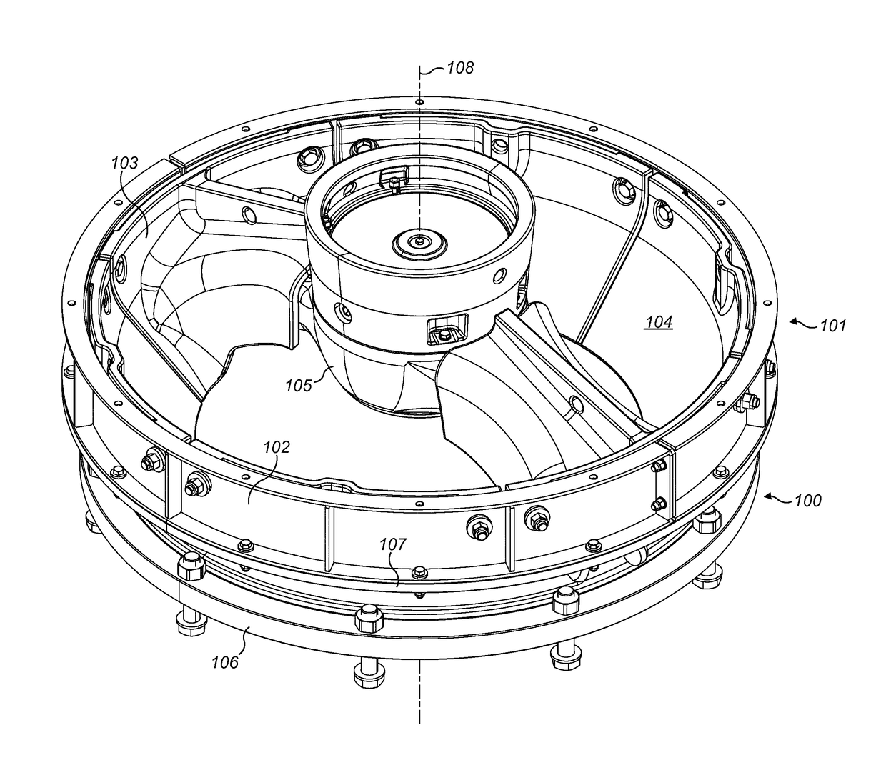
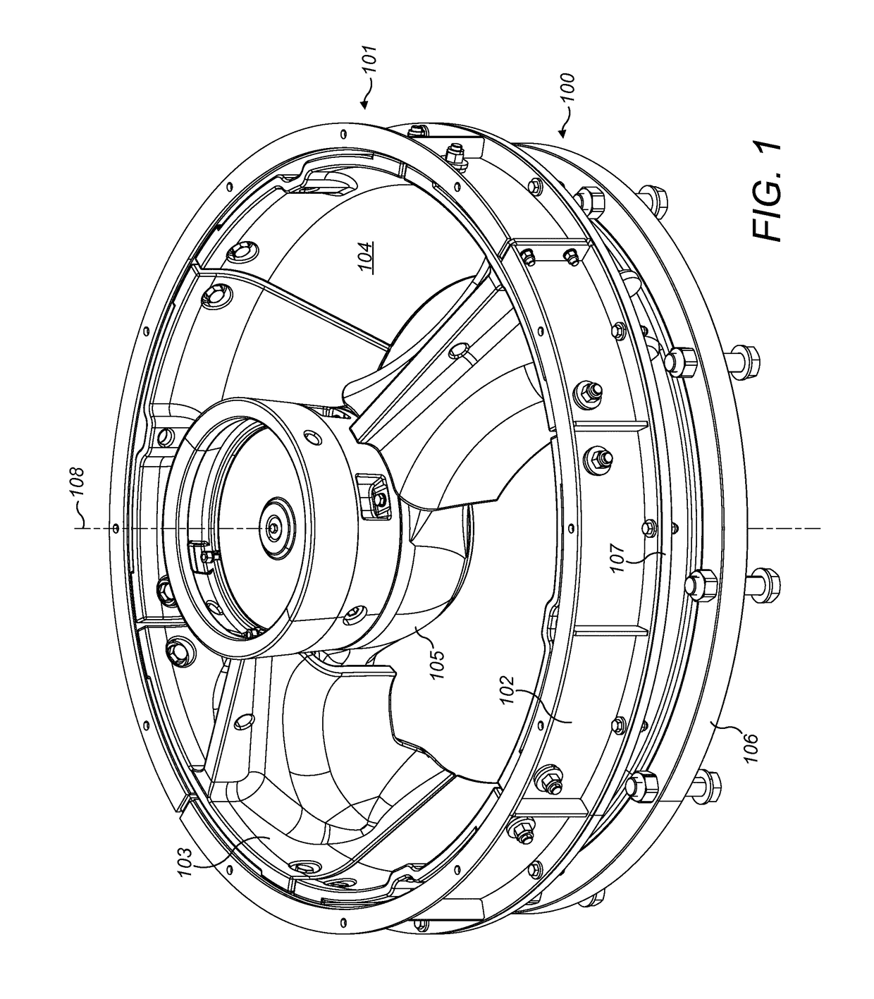
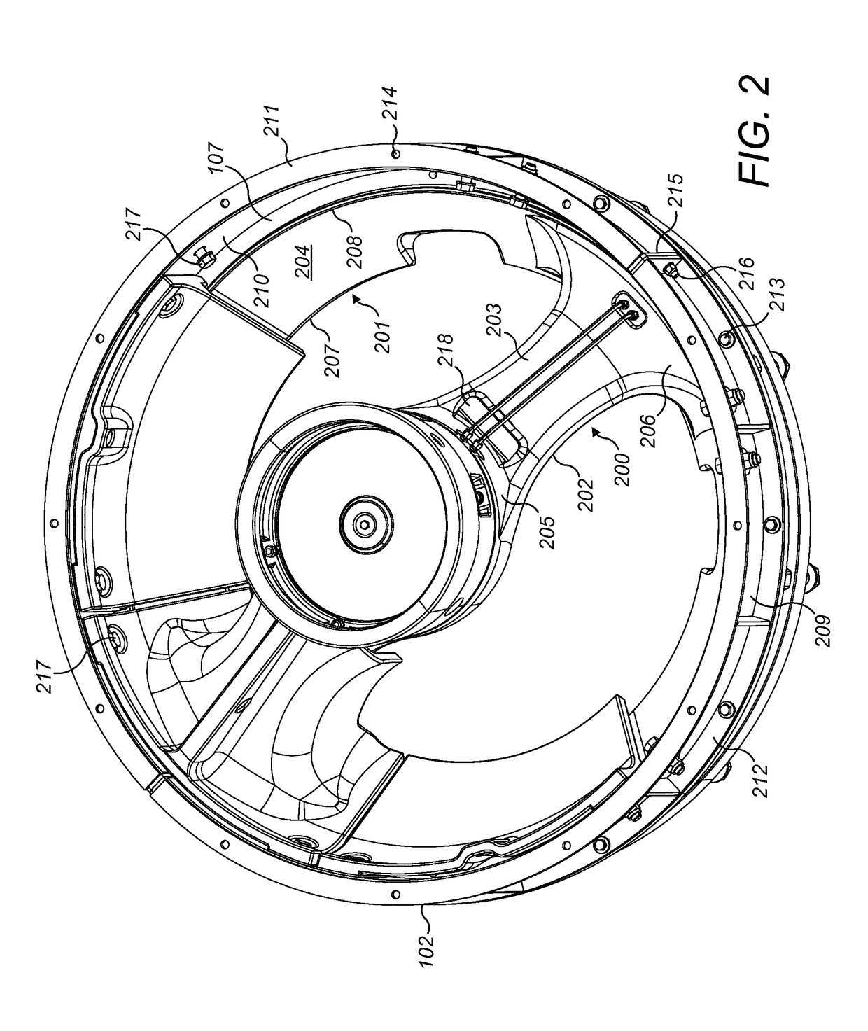
[0038]Referring to FIGS. 1 and 2, a spider of a gyratory crusher is indicated generally by reference 100 and comprises a pair of diametrically opposed arms 200. Arms 200 extend radially outward from a central boss 105 centred on a longitudinal axis 108 extending through spider 100 and a gyratory crusher (not shown) mounted generally axially below spider 100. Each arm 200 comprises a radially innermost region 205 positioned at boss 105 and a radially outermost region 206 positioned at a spider wall indicated generally by reference 201. Each arm 200 therefore represents a bridge extending between boss 105 and an annular spider perimeter wall 201. Each arm 200 comprises a side face 202 an upper face 203 and an underside face (not shown) extending between radially inner and outer regions 205, 206.

[0039]Spider wall 201 is orientated to be angled or declined relative to longitudinal axis 108 such that an axially lowermost edge 207 is positioned closer to axis 108 than an axially upper ann...


PUM


Abstract

A gyratory crusher spider wall shield for releasable mounting to a radially inward facing face of a spider positioned on top of a shell of a gyratory crusher includes a primary protection wall positionable over the inward face of the spider and a rear wall attachable to an outer annular fixating ring positionable axially intermediate a material input hopper and the spider.

Description

FIELD OF INVENTION[0001]The present invention relates to a gyratory crusher spider protection shield and in particular, although not exclusively, to a spider wall shield configured for mounting and dismounting at a spider wall so as to protect the wall from material to be crushed as it falls into the crushing zone.BACKGROUND ART[0002]Gyratory crushers are used for crushing ore, mineral and rock material to smaller sizes. Typically, the crusher comprises a crushing head mounted upon an elongate main shaft. A first crushing shell (referred to as a mantle) is mounted on the crushing head and a second crushing shell (referred to as a concave) is mounted on a frame such that the first and second shells define together a crushing chamber through which the material to be crushed is passed. A driving device positioned at a lower region of the main shaft is configured to rotate an eccentric assembly positioned about the shaft to cause the crushing head to perform a gyratory pendulum movement...

Claims


Application Information

Patent Timeline
IPC IPC(8): B02C2/06B02C2/00F16D55/00F16D65/00
CPCB02C2/06F16D2055/0037F16D65/00B02C2/00
Inventor HALLBERG, ANDERSLARSSON, MIKAEL M.
Owner SANDVIK INTELLECTUAL PROPERTY AB
Why Eureka
Try Eureka