
A horizontally movable vertical shaft rope guide and regulating method thereof

a vertical shaft rope and guide technology, applied in the direction of mine lifts, mining structures, earth-moving mining, etc., can solve the problem of lateral vibration of containers

Inactive Publication Date: 2017-10-26
CHINA UNIV OF MINING & TECH
View PDF0 Cites 5 Cited by
  • Summary
  • Abstract
  • Description
  • Claims
  • Application Information

AI Technical Summary

Benefits of technology

The present invention is a regulating method for the horizontally movable vertical shaft rope guide. The technical effect achieved by this method is that when two hoisting containers meet each other, the cage guide ropes move towards the center and apply a lateral force oriented to the center of the vertical shaft, resulting in the balancing off of the pressure of air flow applied on the hoisting containers and minimizing the impact of air flow. The method is simple in structure, operates smoothly and stably, and is easy to regulate and maintain.

Problems solved by technology

However, as the depth of vertical shaft increases, even tensioned steel wire ropes may exhibit high flexibility; especially, when the primary hoisting container and the secondary hoisting container meet, the air flow generated by the operation of one container may produce lateral force against the other container; consequently, the containers may have lateral vibration, which has impact on operating smoothness and stability of the hoisting containers.

Method used


Image

  • A horizontally movable vertical shaft rope guide and regulating method thereof
  • A horizontally movable vertical shaft rope guide and regulating method thereof
  • A horizontally movable vertical shaft rope guide and regulating method thereof

Examples


Embodiment Construction

[0017]Hereunder one example of the present invention will be further described with reference to the accompanying drawings:

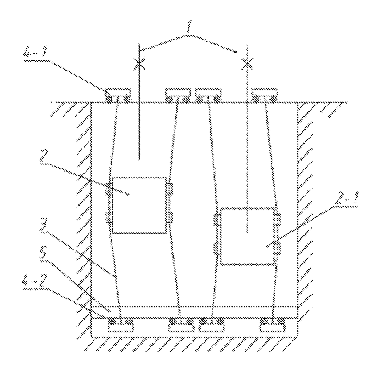
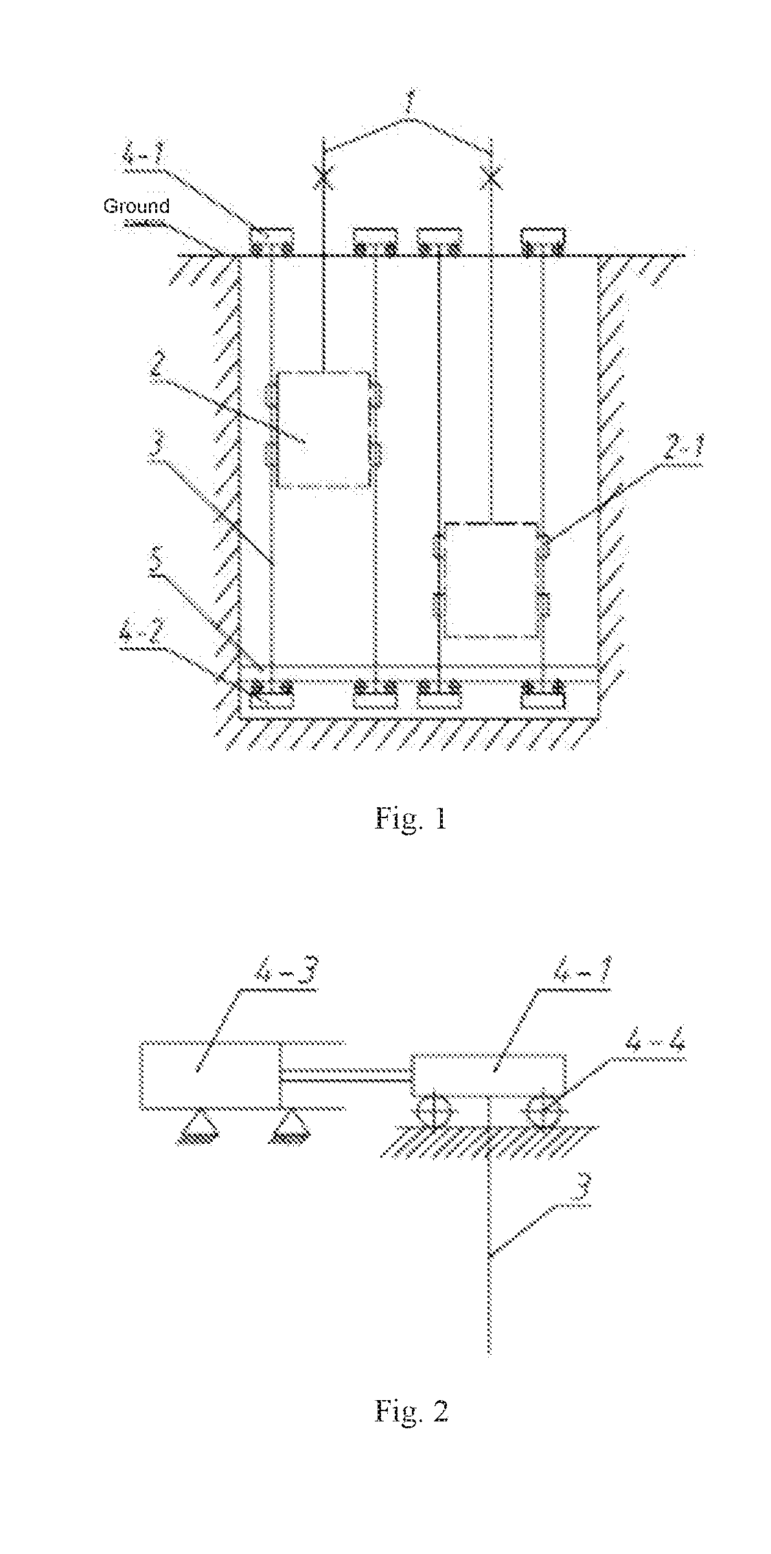
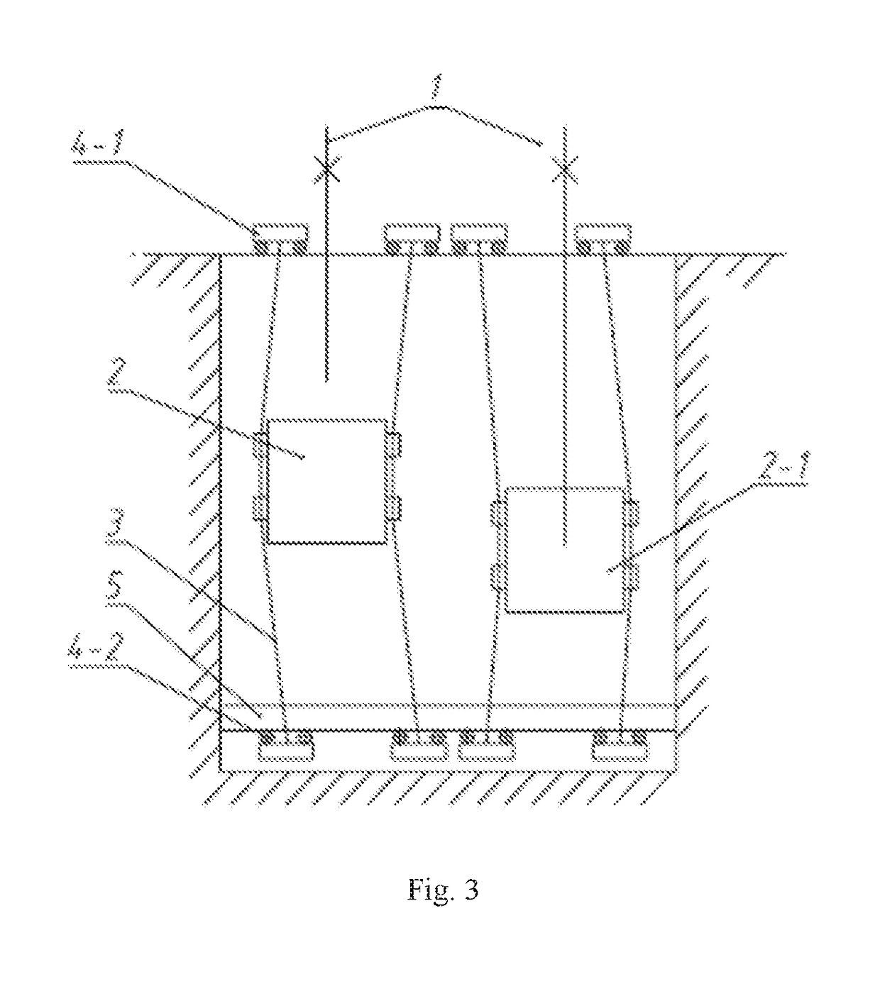
[0018]The horizontally movable vertical shaft rope guide provided in the present invention comprises a hoisting rope 1, and two hoisting containers 2 that are suspended from the tail ends of the hoisting rope 1 and run up and down alternatively, wherein, guide cage lugs 2-1 are arranged symmetrically on two sides of each of the hoisting containers 2, cage guide ropes 3 are led through the guide cage lugs 2-1 on the two sides respectively, a tensioner 4-1 arranged on the ground at the shaft top is connected to the upper end of each cage guide rope 3, and a connector 4-2 arranged under a steel slot 5 at the shaft bottom is connected to the lower end of each cage guide rope 3; each tensioner 4-1 arranged on the ground at the shaft top is opposite to the corresponding connector 4-2 arranged under the steel slot 5 at the shaft bottom, a hydraulic cylinder 4-3 is conn...


PUM


Abstract

The present invention relates to a horizontally movable vertical shaft rope guide and a regulating method thereof which are suitable for guiding of hoisting containers in vertical shafts. The vertical shaft rope guide comprises a hoisting rope, and two hoisting containers suspended from the tail ends of the hoisting rope, wherein, cage guide ropes are led through guide cage lugs arranged on the two sides respectively, a tensioner arranged on the ground at the shaft top is connected to the upper end of each cage guide rope, and a connector arranged under a steel slot at the shaft bottom is connected to the lower end of each cage guide rope; a hydraulic cylinder is connected at the other side of each tensioner and the corresponding connector, and the hydraulic cylinder is connected to the tensioner or connector. During hoisting in the vertical shaft, the hydraulic cylinders are controlled to act in advance, to push the tensioners or connectors to move towards the center between the two hoisting containers, so that the cage guide ropes led through the guide cage lugs on the two sides of the hoisting containers get close to each other at the same time and wrap the hoisting container; thus, the horizontal displacement of the hoisting containers is restrained, and the impact of air flow on the two hoisting containers is minimized when the two hoisting containers meet.

Description

I. FIELD OF THE INVENTION[0001]The present invention relates to a horizontally movable vertical shaft rope guide and a regulating method thereof, which are especially suitable for guiding of hoisting containers in vertical shafts.II. BACKGROUND OF THE INVENTION[0002]In some vertical shaft hoisting systems, tensioned steel wire ropes are selected as cage guides for hoisting containers. However, as the depth of vertical shaft increases, even tensioned steel wire ropes may exhibit high flexibility; especially, when the primary hoisting container and the secondary hoisting container meet, the air flow generated by the operation of one container may produce lateral force against the other container; consequently, the containers may have lateral vibration, which has impact on operating smoothness and stability of the hoisting containers.III. CONTENTS OF THE INVENTION[0003]Technical Problem:[0004]To overcome the drawbacks in the prior art, the present invention provides a horizontally mova...

Claims


Application Information

Patent Timeline
Patent Type & Authority Applications(United States)
IPC IPC(8): B66B17/00B66B19/00
CPCB66B19/00B66B17/00E21D7/02
Inventor ZHU, ZHENCAICAO, GUOHUAWANG, YANDONGYAN, LUPENG, WEIHONGPENG, YUXINGZHOU, GONGBOLI, WEISHEN, GANG
Owner CHINA UNIV OF MINING & TECH
Learn More