
Drum brake which can be operated by an electric motor

a technology of electric motors and drum brakes, applied in the direction of brake systems, mechanical devices, transportation and packaging, etc., can solve the problems of increasing the complexity of manufacturing in that area, unable to permit simple variations in the context of mass production, and problems, etc., to achieve simple and efficient adaptation of drum brake modules and high efficiency

Inactive Publication Date: 2017-10-26
CONTINENTAL TEVES AG & CO OHG
View PDF8 Cites 1 Cited by
  • Summary
  • Abstract
  • Description
  • Claims
  • Application Information

AI Technical Summary

Benefits of technology

The present invention proposes a solution to the problem of requiring highly individual adaptations to a wide variety of components of the drum brake module for different motor vehicle models. The invention provides a cable pull guide body with a curved cable receptacle and U-shaped cross section that can be easily and adaptable to different installation conditions, while maintaining a constant efficiency of the drum brake module over the service life. The cable pull guide channel formed by the cable pull guide body may be narrowed in funnel-shaped fashion and equipped with cams to prevent an undesired escape of a slack cable, in particular in a released state of the brake. The cable pull guide body is fastened to the anchor plate with at least one detent means. The cable pull guide body may be composed of a plastics material that is resistant to high temperatures and may be welded or riveted non-detachably to the anchor plate. The invention provides a simpler and more efficient solution for adapting a drum brake module to different motor vehicle applications.

Problems solved by technology

Parking brake cable pull systems with a central cable pull actuator are disadvantageous because, at a vehicle manufacturer, separate installation and articulation of the cable pull on the wheel brake is necessary, such that the final installation of cable pull actuator, cable pull and wheel brake can only be performed on the assembly line at the vehicle manufacturer, which increases the complexity of manufacture in that area.
This type of construction requires not only an electric motor which is dimensioned to be of relatively high power but also further very specifically designed components, and therefore does not permit simple variation in the context of mass production.
Problems arise in the event of hot shutdown.

Method used


Image

  • Drum brake which can be operated by an electric motor
  • Drum brake which can be operated by an electric motor
  • Drum brake which can be operated by an electric motor

Examples


Embodiment Construction

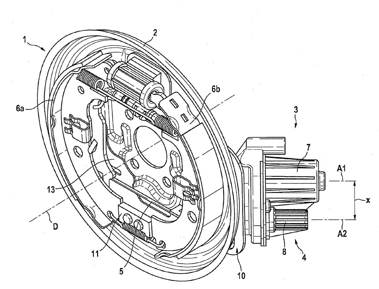
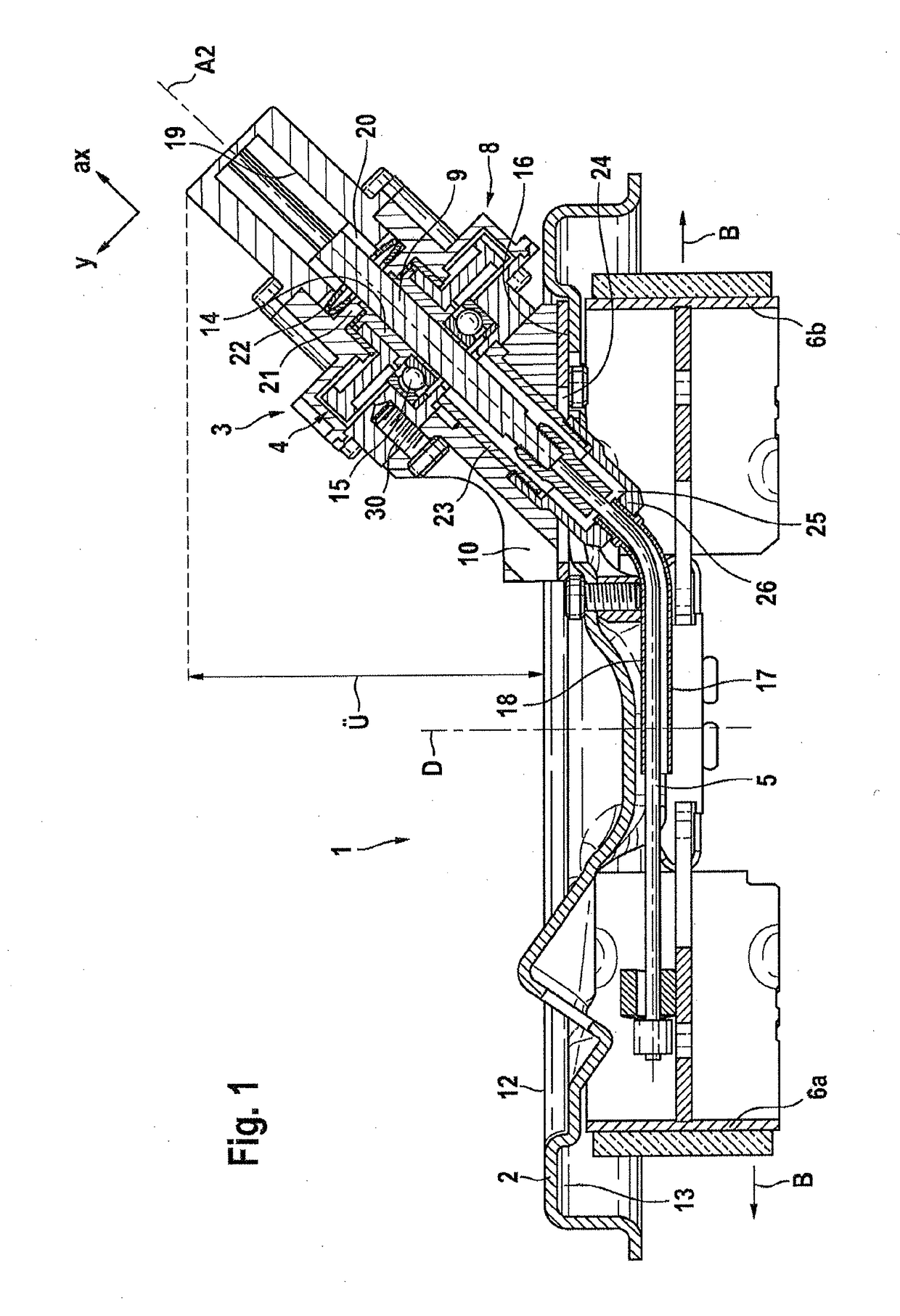
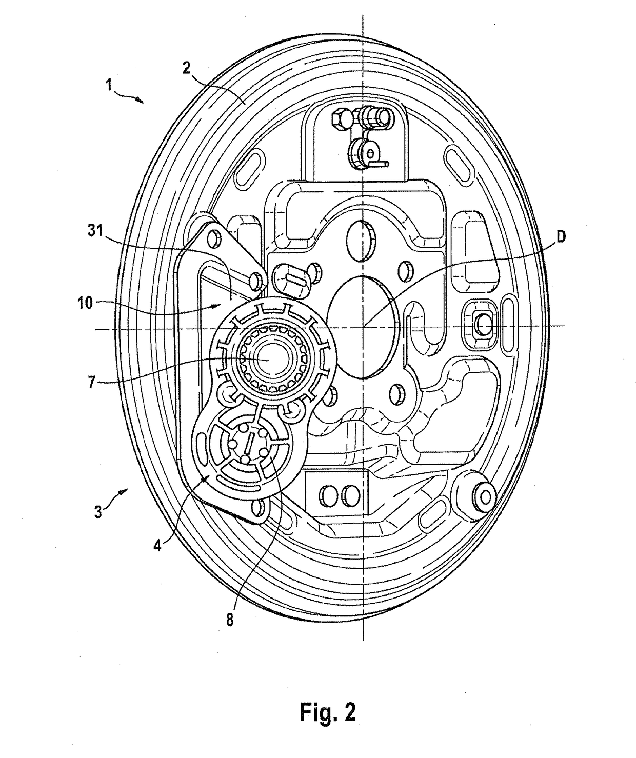
[0021]A known electromotively actuable drum brake module 1 for arrangement on axle components of a motor vehicle comprises, as per FIG. 1, an anchor plate 2 with brake pads 6a,b mounted thereon, which brake pads are provided within a brake drum (not shown).

[0022]Fastened to an opposite side of the anchor plate 2 is an electromotively driven cable pull actuator 3 which, by way of a gearing 4 and a cable pull 5 connected downstream, engages on one or more of the brake pads 6a,b such that said brake pad(s) 6a,b can perform an actuation movement B in the direction toward the brake drum in order to realize a service brake and / or parking brake function. A support device 11 may be provided between the brake pads 6a,b.

[0023]The gearing 4 comprises a gearing housing 8 which accommodates or at least bears the motor 7. The motor 7 consumes direct-current voltage, is mechanically or electronically commutated, and is of a standard type that is available at low cost.

[0024]FIG. 1 illustrates, at ...


PUM


Abstract

A drum brake module for motor vehicles, the drum brake module being driven by an electric motor and having at least one parking brake function, includes an electromechanical cable pull actuator which is fastened on the anchor plate with the aid of an adapter. The adapter is designed as a one-piece, thin walled frame having at least one fastening flange for receiving the cable pull actuator and is held in place on the anchor plate.

Description

CROSS REFERENCE TO RELATED APPLICATIONS[0001]This application is a divisional of U.S. application Ser. No. 14 / 895,299, filed Dec. 2, 2015, which is national phase application of U.S. National Phase Application of PCT International Application No. PCT / EP2014 / 061514, filed Jun. 3, 2014, which claims priority to German Patent Application No. 10 2013 210 528.2, filed Jun. 6, 2013, the contents of such application being incorporated by reference herein.FIELD OF THE INVENTION[0002]The present invention relates to an electrically actuated drum brake, in particular electromotively actuated drum brake module, with improved cable pull actuator arrangement for motor vehicles, comprising an electromechanical cable pull actuator which is arranged on an outer side of the anchor plate and which serves for driving a rotation-translation converter for converting a rotational drive input rotary movement into a translational actuation movement (B) of brake pads, which brake pads are arranged on an inn...

Claims


Application Information

Patent Timeline
Patent Type & Authority Applications(United States)
IPC IPC(8): F16D65/22B60T7/10F16D51/00F16D51/28B60T7/08F16D121/24F16D125/60
CPCF16D2121/24F16D2125/60B60T7/085F16D51/28F16D51/00F16D65/22B60T7/102
Inventor BACH, UWEHOFFMANN, JENSGORRISSEN, NICLASRITTER, WOLFGANGSEFO, AHMEDVON HAYN, HOLGER
Owner CONTINENTAL TEVES AG & CO OHG
Learn More