Pneumatic Tire

Inactive Publication Date: 2017-11-02
YOKOHAMA RUBBER CO LTD
View PDF4 Cites 7 Cited by
  • Summary
  • Abstract
  • Description
  • Claims
  • Application Information

AI Technical Summary

Benefits of technology

[0006]The present technology provides a pneumatic tire capable of achieving good wet performance, dry

Problems solved by technology

However, by simply increasing the number of grooves, tread rigidity decreases and thus sufficient dry performance and uneven wear resistance performance cannot be obtained.
Additionally, depending on the shape and arrangement of the grooves, pass-by noise is more likely to be caused thus decreasing noise performance.
However, with increasing demands for faster vehicle speeds brought about by developments in high performanc

Method used


Image

  • Pneumatic Tire
  • Pneumatic Tire
  • Pneumatic Tire

Examples


examples

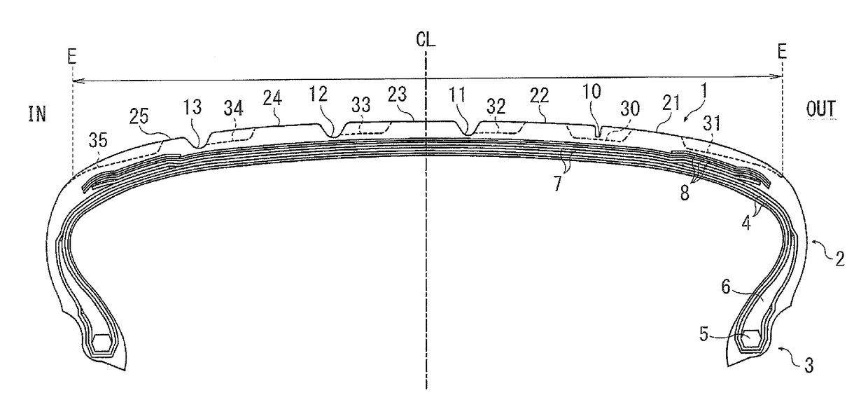
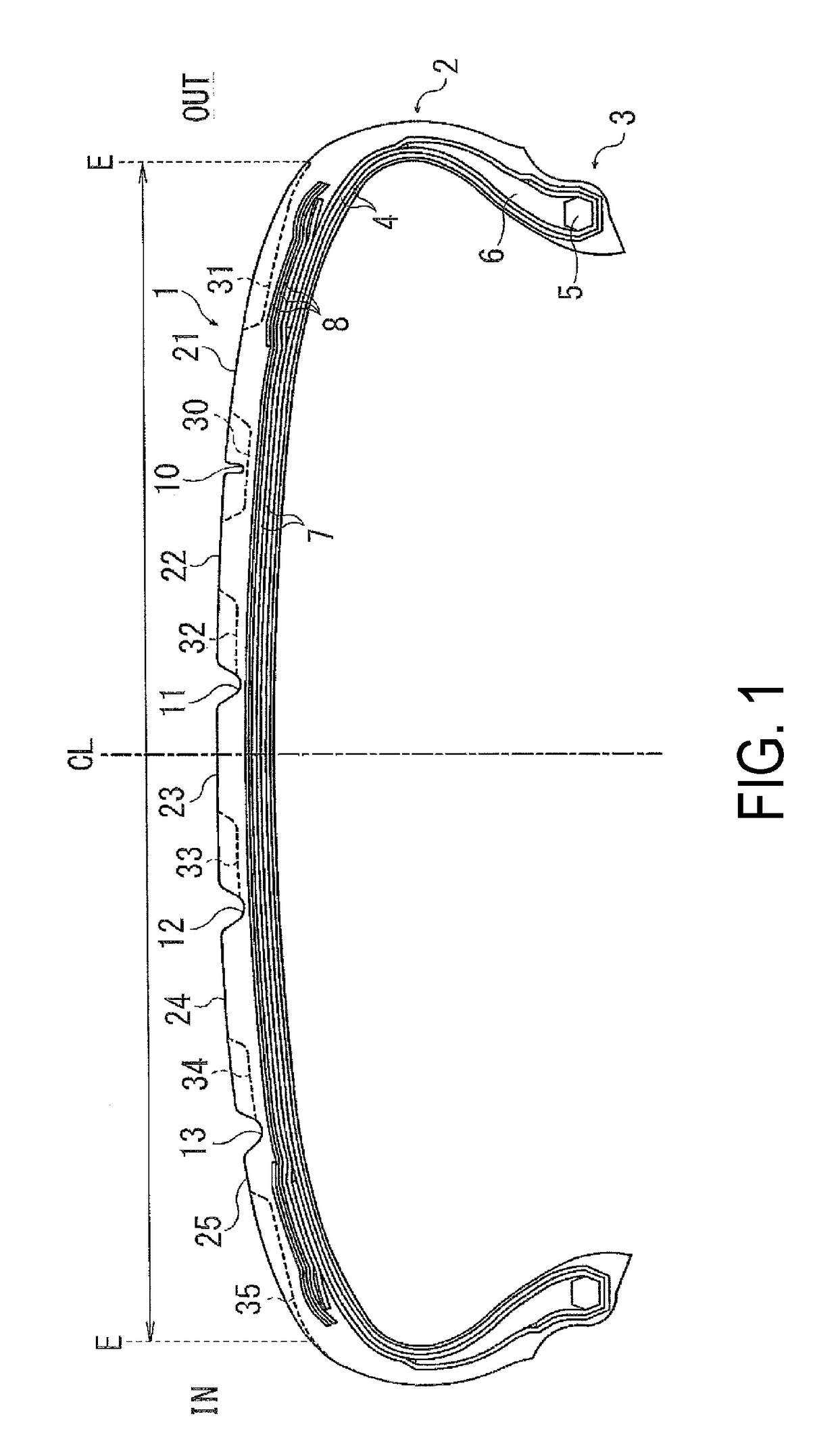
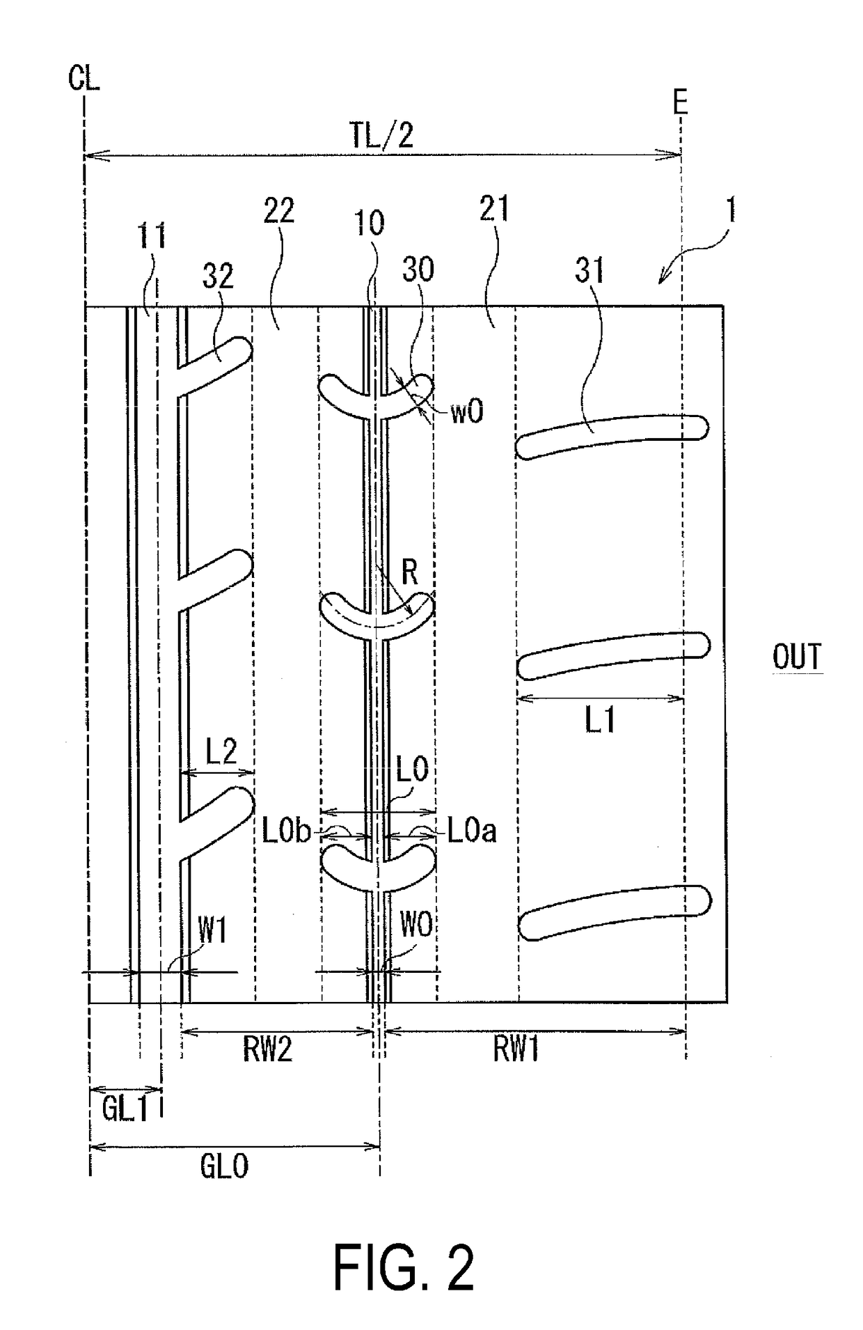
[0049]Seventeen types of pneumatic tires corresponding to Conventional Example 1, Comparative Examples 1 and 2, and Examples 1 to 14 were manufactured. The tire size was 285 / 35ZR20 and the tires all included the reinforcement structure illustrated in FIG. 1. Other specifications including base tread pattern, groove width of the narrow groove and the first to third main grooves (for the narrow groove, the ratio with respect to the first main groove is also indicated), distance from the tire equator of the narrow groove and the first to third main grooves (ratio with respect to the half-width TL / 2 of the ground contact width), length L0 in the tire width direction of the lug groove (ratio with respect to the ground contact width TL), length L0a in the tire width direction of the portion of the lug groove on the side where the first rib is disposed (ratio with respect to the width of the first rib), length in the tire width direction of the portion of the lug groove on the side where t...


PUM


Abstract

A pneumatic tire includes a narrow groove disposed on a vehicle outer side of a tire equator in the tread portion extending in the tire circumferential direction, wherein the narrow groove has a groove width of from 1 mm to 6 mm; and a plurality of lug grooves disposed in the tread portion that intersect with the narrow groove and include terminating ends on opposite sides, wherein the plurality of lug grooves are each curved toward one side in the tire circumferential direction.

Description

TECHNICAL FIELD[0001]The present technology relates to a pneumatic tire, and more specifically relates to a pneumatic tire capable of achieving good wet performance, dry performance, uneven wear resistance performance, and noise performance in a highly compatible manner.BACKGROUND ART[0002]There is a demand for conventional pneumatic tires to be enhanced in a highly compatible manner in terms of dry performance (for example, steering stability performance and travel time on dry road surfaces) and wet performance (for example, steering stability performance and hydroplaning resistance performance on wet road surfaces). Enhancements in terms of tire wear resistance performance (in particular uneven wear) and noise performance (for example, pass-by noise) are also demanded in addition to these performances.[0003]One known method of improving wet performance includes disposing a plurality of grooves in a tread portion of a pneumatic tire to improve drainage properties. However, by simpl...

Claims


Application Information

Patent Timeline
IPC IPC(8): B60C11/03B60C1/00B60C9/18
CPCB60C11/0302B60C1/0016B60C1/0008B60C9/18B60C11/1392B60C11/0304B60C2011/0388B60C11/032B60C2011/0353B60C2200/04B60C2011/0381B60C2011/0393B60C2011/039B60C11/03B60C11/13B60C2011/0341B60C2011/0348
Inventor ICHIMURA, AKIHIRO
Owner YOKOHAMA RUBBER CO LTD
Why Eureka
Try Eureka