Pneumatic tire having tread with axially adjacent block chamfer and rib chamfer

Active Publication Date: 2006-12-05
THE GOODYEAR TIRE & RUBBER CO
View PDF35 Cites 9 Cited by
  • Summary
  • Abstract
  • Description
  • Claims
  • Application Information

AI Technical Summary

Benefits of technology

[0004]The present invention is directed to a tire with a tread designed fo

Problems solved by technology

However, since enhanced traction is best achieved by providing most biting edges to the tread pattern, while

Method used


Image

  • Pneumatic tire having tread with axially adjacent block chamfer and rib chamfer
  • Pneumatic tire having tread with axially adjacent block chamfer and rib chamfer
  • Pneumatic tire having tread with axially adjacent block chamfer and rib chamfer

Examples


Embodiment Construction

[0018]The following language is of the best presently contemplated mode or modes of carrying out the invention. This description is made for the purpose of illustrating the general principals of the invention and should not be taken in a limiting sense. The scope of the invention is best determined by reference to the appended claims.

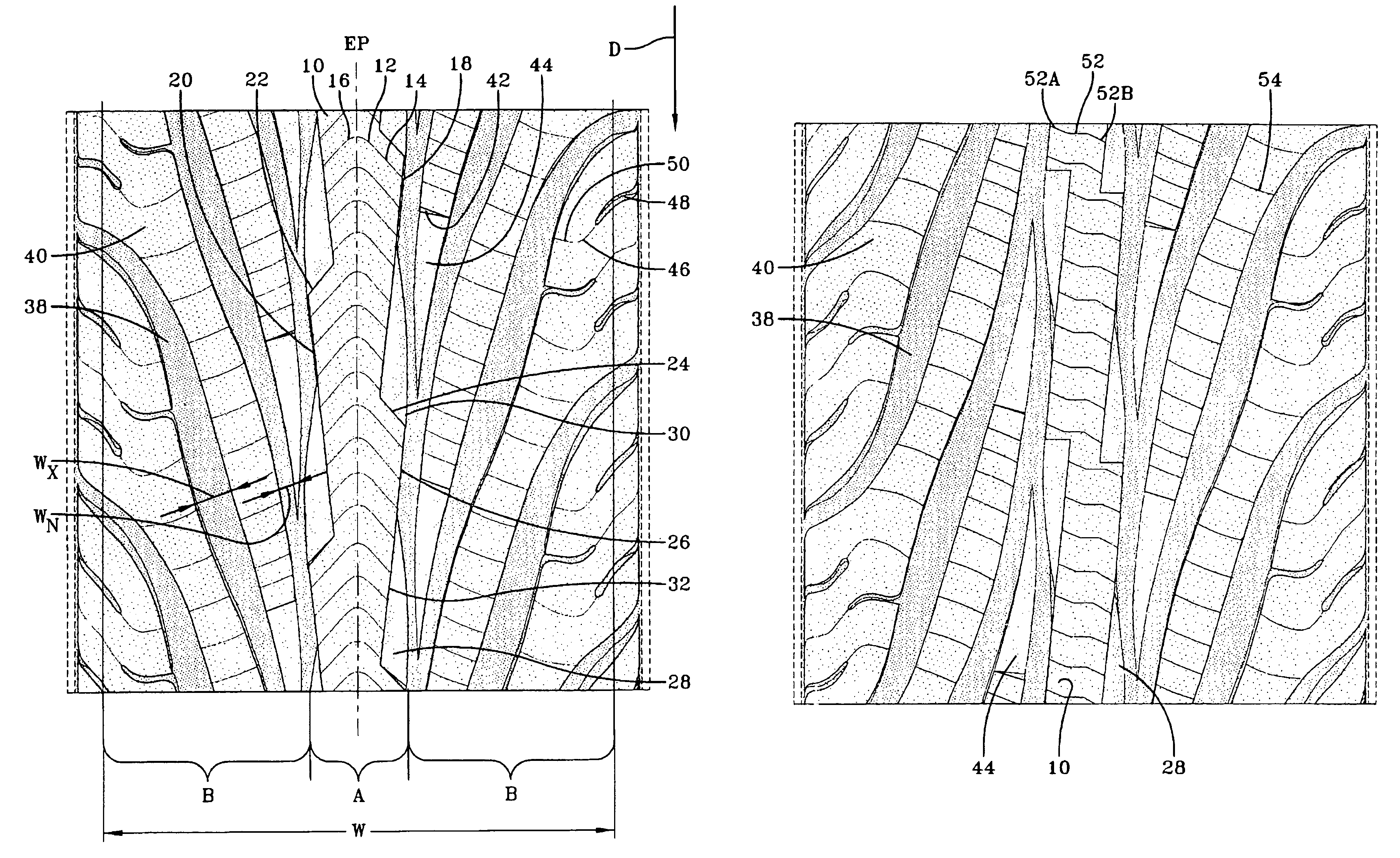
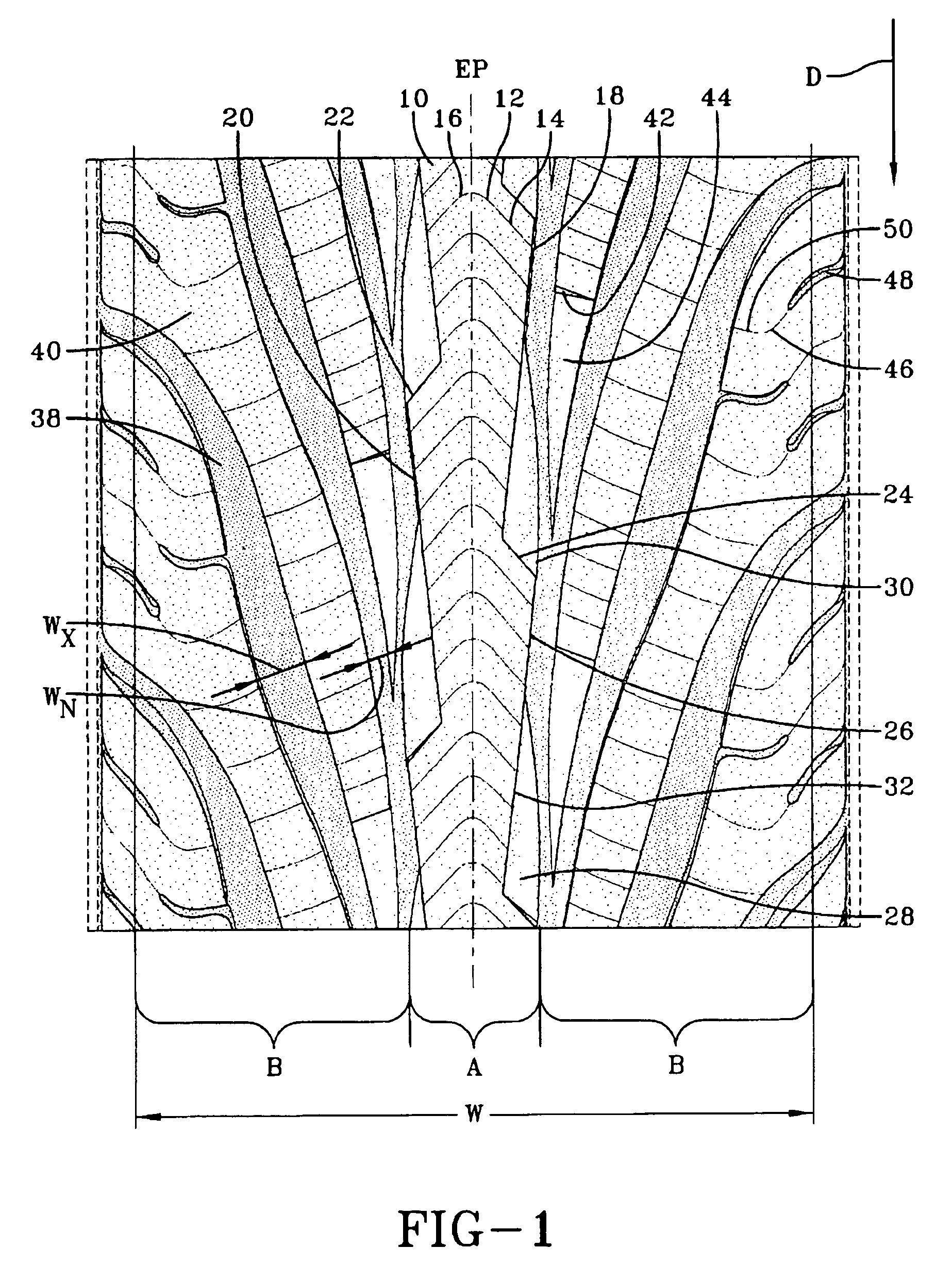
[0019]FIG. 1 is a plan view of a tread for a tire in accordance with the present invention. The tread configuration is intended for use on a passenger vehicle, or a light truck. The illustrated tread has a directional configuration, with the preferred direction for forward moving being that shown by the arrow D. The tread is divided into three regions, a central region A, and two side regions B. The central region is centered on the equatorial plane of the tire and has a width of approximately 15% to 30% of the tread width W, the tread width being measured from one tread shoulder to the opposing tread shoulder.

[0020]When operating in winter driving cond...


PUM


Abstract

A tire tread for a pneumatic tire has a center rib and a series of steeply slanted grooves in each side region of the tread, the circumferentially adjacent grooves form blocks extending through the tread side regions. The center rib has a serrated configuration along each lateral side and a supporting chamfer extending from each serration point. Adjacent to each rib chamfer is a chamfer extending from the axially innermost point of the rib at the junction of two adjacent steeply slanted grooves. The rib is provided with high density siping. The tread blocks are siped wherein the siping density decreases from the tread center to the tread shoulders.

Description

FIELD OF THE INVENTION[0001]The present invention is directed to a tire tread with improved performance in snow and ice and in regular running conditions. The tread is provided with a central rib and a series of steeply slanted grooves adjacent the rib. The rib and the adjacent tread blocks are configured to provide for improved all weather performance.BACKGROUND OF THE INVENTION[0002]In a conventional tire for typical use as on a passenger car or light truck, the tire tread is provided with a series of grooves, either circumferentially or laterally extending, or a combination of both, to form a plurality of blocks.[0003]The goals of a tire during winter driving condition are to maintain good contact with the road, while providing for enhanced traction. However, since enhanced traction is best achieved by providing most biting edges to the tread pattern, while road contact is achieved by providing more surface area for tread contact, these goal are often conflicting.SUMMARY OF THE I...

Claims


Application Information

Patent Timeline
IPC IPC(8): B60C11/03B60C11/12B60C11/13
CPCB60C11/0302B60C11/12B60C11/13B60C11/1384B60C11/033B60C2011/0388Y10S152/03B60C2011/0374
Inventor RATLIFF, JR., BILLY JOE
Owner THE GOODYEAR TIRE & RUBBER CO
Why Eureka
Try Eureka