Hot air drying equipment for corrugated case printing machine

A technology for hot air drying and corrugated boxes, which is applied to printing machines, general parts of printing machinery, printing, etc. It can solve the problems of different drying strength, different shrinkage degrees, and different ink shrinkage degrees, so as to avoid gelatinization and improve The effect of traction

Inactive Publication Date: 2020-11-20
广州佳优华信息科技有限公司
View PDF0 Cites 0 Cited by
  • Summary
  • Abstract
  • Description
  • Claims
  • Application Information

AI Technical Summary

Problems solved by technology

[0002] Corrugated box is the most widely used packaging product. During the production of corrugated boxes, it is necessary to mark the surface of the corrugated cardboard, transfer ink from the printing plate to the corrugated cardboard, and the printed corrugated cardboard needs to pass The hot air drying equipment dries the ink on its surface, but when drying the corrugated cardboard with printing on multiple sides, the corrugated cardboard is directly put into the hot air drying equipment, resulting in different drying strengths on mu

Method used


Image

  • Hot air drying equipment for corrugated case printing machine
  • Hot air drying equipment for corrugated case printing machine
  • Hot air drying equipment for corrugated case printing machine

Examples


Embodiment 1

[0024] as attached figure 1 to attach Figure 5 Shown:

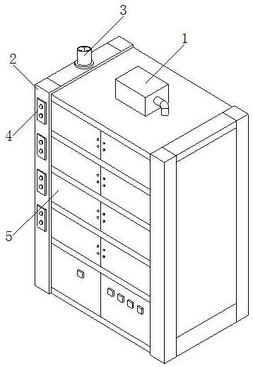
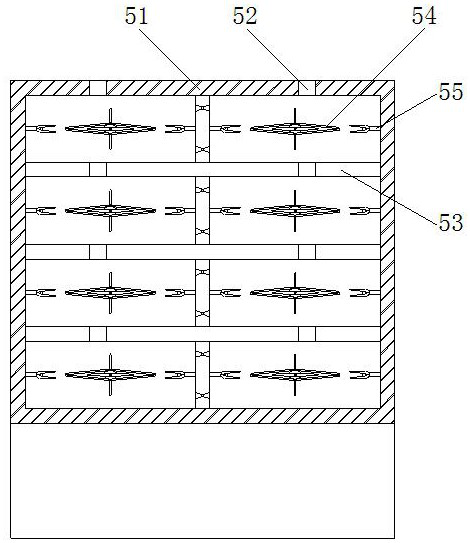
[0025] The invention relates to a corrugated box printing machine hot air drying equipment, the structure of which includes a fan 1, a side support plate 2, a moisture discharge pipe 3, a control panel 4, and a drying box 5. The fan 1 is fixedly installed on the top of the drying box 5, and the side The support plate 2 is welded to the side end of the drying box 5, the upper end of the side support plate 2 is embedded with a moisture discharge pipe 3, and the moisture discharge pipe 3 is connected with the interior of the drying box 5, and the control panel 4 is installed on the side support plate 2 front surface, and the control panel 4 is electrically connected with the fan 1, the drying box 5 includes a box body 51, a hot air inlet 52, a spacer 53, a clamping mechanism 54, and a welting mechanism 55. The top of the box body 51 is embedded There is a hot air inlet 52, and the hot air inlet 52 is connected with the fa...

Embodiment 2

[0032] as attached Figure 6 to attach Figure 8 Shown:

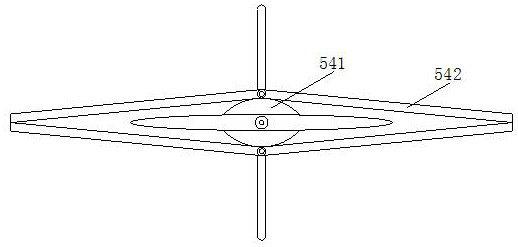
[0033] Wherein, the welt mechanism 55 includes a fixed sleeve 551, a telescopic hose 552, an outreach mechanism 553, a positioning shaft 554, a return spring 555, and a second magnetic block 556, and the right end of the fixed sleeve 551 is fixedly installed on the box. body 51 inside surface, the inside of the fixed sleeve 551 is provided with a telescopic hose 552, and the left end of the telescopic hose 552 is fixed to the right end of the abduction mechanism 553, and the middle part of the abduction mechanism 553 is provided with a positioning shaft 554. The inner side of the extension mechanism 553 is fixed with the return spring 555, and the inner surface of the left end of the extension mechanism 553 is welded with a second magnetic block 556. The telescopic hose 552 has a folded structure and is made of thermoplastic polyurethane elastomer rubber, with Certain ductility and high temperature resistance are bene...


PUM


Abstract

The invention discloses hot air drying equipment for a corrugated case printing machine. The hot air drying equipment structurally comprises a draught fan, side supporting plates, a dehumidification pipe, control panels and a drying box, wherein the draught fan is fixedly installed at the top of the drying box, the side supporting plates are welded to the side ends of the drying box, and the dehumidification pipe is fixedly installed at the upper ends of the side supporting plate in an embedded manner. In the drying process, hot air is guided into conduction pipes through air inlets in the front ends of connecting supporting plates, so expansion films expand and swell, at the moment, the angle between swinging plate bodies increases, the four outer sides of a corrugated plate are propped open, magnetic attraction is carried out through second magnetic blocks on laminating plates and first magnetic blocks, meanwhile the laminating plates rotate around positioning shafts, when the laminating plates are attached to the surfaces of the swinging plate bodies, collision plates and the surfaces of the swinging plate bodies maintain laminating strength, the traction on the outer side on the corrugated plate is improved, large shrinkage occurring to the corrugated plate in the drying process is prevented, and ink printing gelatinization of the corrugated plate during drying is avoided.

Description

technical field [0001] The invention relates to the field of corrugated carton machinery, and more specifically, relates to a hot air drying device for a corrugated carton printing machine. Background technique [0002] Corrugated box is the most widely used packaging product. During the production of corrugated boxes, it is necessary to mark the surface of the corrugated cardboard, transfer ink from the printing plate to the corrugated cardboard, and the printed corrugated cardboard needs to pass The hot air drying equipment dries the ink on its surface, but when drying the corrugated cardboard with printing on multiple sides, the corrugated cardboard is directly put into the hot air drying equipment, resulting in different drying strengths on multiple sides of the corrugated cardboard, resulting in multiple corrugated cardboards. The degree of shrinkage of the surface is different, resulting in different degrees of ink shrinkage on each board surface, and the bottom surfac...

Claims


Application Information

Patent Timeline
IPC IPC(8): B41F23/04B41F21/00
CPCB41F21/00B41F23/04B41F23/0443B41F23/0466
Inventor 江海霞
Owner 广州佳优华信息科技有限公司
Why Eureka
Try Eureka