Steering System

a steering system and steering wheel technology, applied in the direction of steering parts, vehicle components, transportation and packaging, etc., can solve the problem of unstable clamping force, and achieve the effect of stable clamping force and improved vibration rigidity

Inactive Publication Date: 2017-11-02
JTEKT CORP
View PDF0 Cites 8 Cited by
  • Summary
  • Abstract
  • Description
  • Claims
  • Application Information

AI Technical Summary

Benefits of technology

[0006]One object of the present invention is to provide a steering system with a stable clamping force and an improved vibration rigidity.

Problems solved by technology

Therefore, the force (clamping force) of the clamping rod clamping the side plates tends to vary in accordance with the position of the clamping rod in the elongated tilt grooves, so that the clamping force tends to be unstable.

Method used


Image

  • Steering System
  • Steering System
  • Steering System

Examples


Embodiment Construction

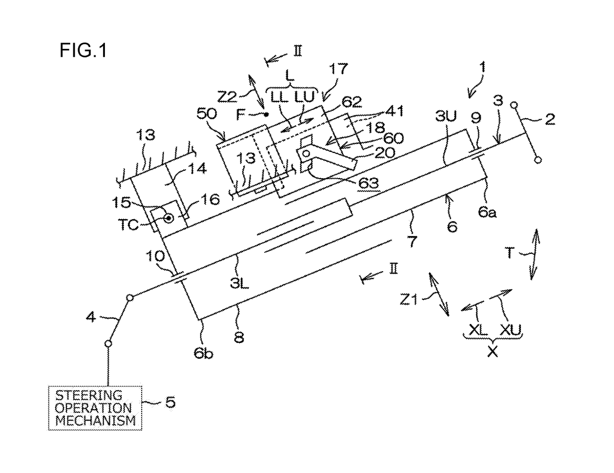
[0017]Hereinafter, embodiments of the present invention will be described in detail with reference to the accompanying drawings. FIG. 1 is a schematic side view illustrating a steering system 1 according to an embodiment of the present invention. Referring to FIG. 1, the steering system 1 includes a steering shaft 3, a cylindrical column jacket 6, an intermediate shaft 4, and a steering operation mechanism 5. An end (axially upper end) of the steering shaft 3 is coupled to a steering member 2 such as a steering wheel. The steering system 1 turns steered wheels (not illustrated) in accordance with steering of the steering member 2. The steering operation mechanism 5 may be, for example, but not limited to, a rack-and-pinion mechanism.

[0018]The upper side in a column axial direction X that is the axial direction of the steering shaft 3 is hereinafter referred to as an axially upper side XU, and the lower side in the column axial direction X is hereinafter referred to as an axially low...


PUM


Abstract

A column jacket includes a pair of facing portions facing each other, and a stepped portion which extends in a direction that intersects with a column axial direction and at which an outer surface of the corresponding facing portion projects outward halfway toward an end side of the column jacket. Tilt grooves are formed in respective side plates of an upper bracket fixed to a vehicle body. A clamping mechanism including a clamping shaft inserted through the tilt grooves clamps the side plates to bend the side plates such that an end of each side plate on the extending direction upper side is displaced toward the corresponding facing portion. The stepped portion is located between a fulcrum portion serving as a fulcrum when the corresponding side plate is bent by being clamped by the clamping mechanism and the corresponding tilt groove, in an extending direction of the side plates.

Description

INCORPORATION BY REFERENCE[0001]The disclosure of Japanese Patent Application No. 2016-091678 filed on Apr. 28, 2016 including the specification, drawings and abstract, is incorporated herein by reference in its entirety.BACKGROUND OF THE INVENTION1. Field of the Invention[0002]The invention relates to a steering system.2. Description of the Related Art[0003]There is known a steering system that improves the rigidity against vibration (vibration rigidity) by clamping a bracket that is attached to the vehicle body and thereby bringing an outer column and the bracket into contact with each other. For example, in an electric power steering system disclosed in Japanese Patent Application Publication No. 2007-223383 (JP 2007-223383 A), an outer column has contact surfaces extending from its end face on the front side of the vehicle body toward the rear of the vehicle body. In this electric power steering system, a clamping rod inserted through elongated tilt grooves formed in respective ...

Claims


Application Information

Patent Timeline
Patent Type & Authority Applications(United States)
IPC IPC(8): B62D1/184B62D1/187B62D1/185
CPCB62D1/184B62D1/185B62D1/187
Inventor YOSHIMURA, SATOKI
Owner JTEKT CORP
Why Eureka
Try Eureka