Heat source system managing device, heat source system managing method, and program

Active Publication Date: 2017-11-02
HITACHI LTD
View PDF17 Cites 4 Cited by
  • Summary
  • Abstract
  • Description
  • Claims
  • Application Information

AI Technical Summary

Benefits of technology

The invention is a device that manages a heat source system, improving its energy efficiency. This means the device helps to save energy when using the heat source system.

Problems solved by technology

On the other hand, in sectors of housing and business, with spread of life styles in which comfort or convenience is pursued, energy consumption has increased yearly.

Method used


Image

  • Heat source system managing device, heat source system managing method, and program
  • Heat source system managing device, heat source system managing method, and program
  • Heat source system managing device, heat source system managing method, and program

Examples


embodiment

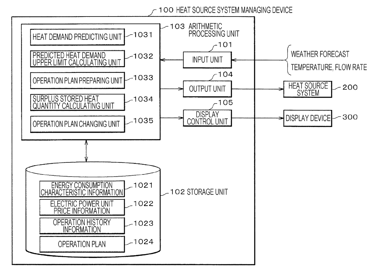
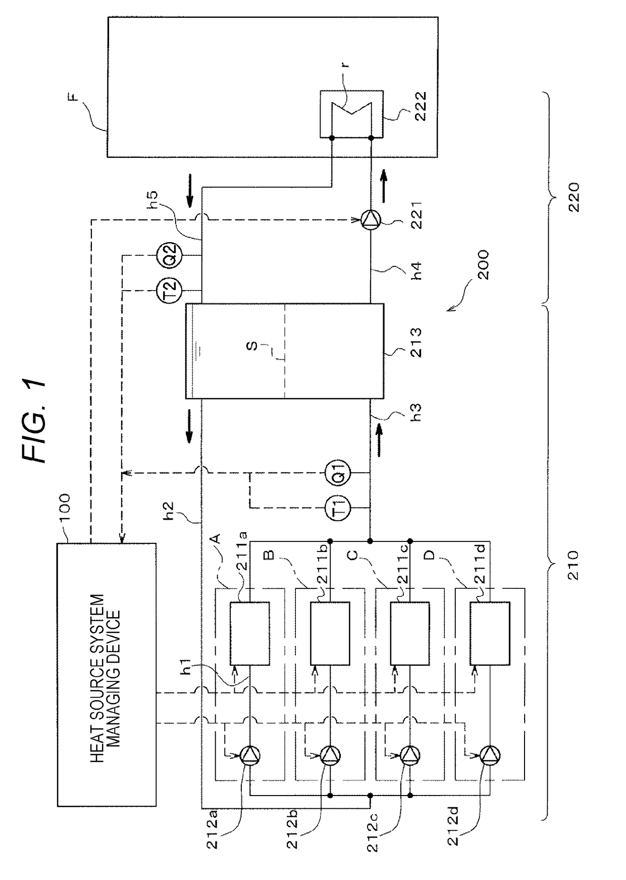
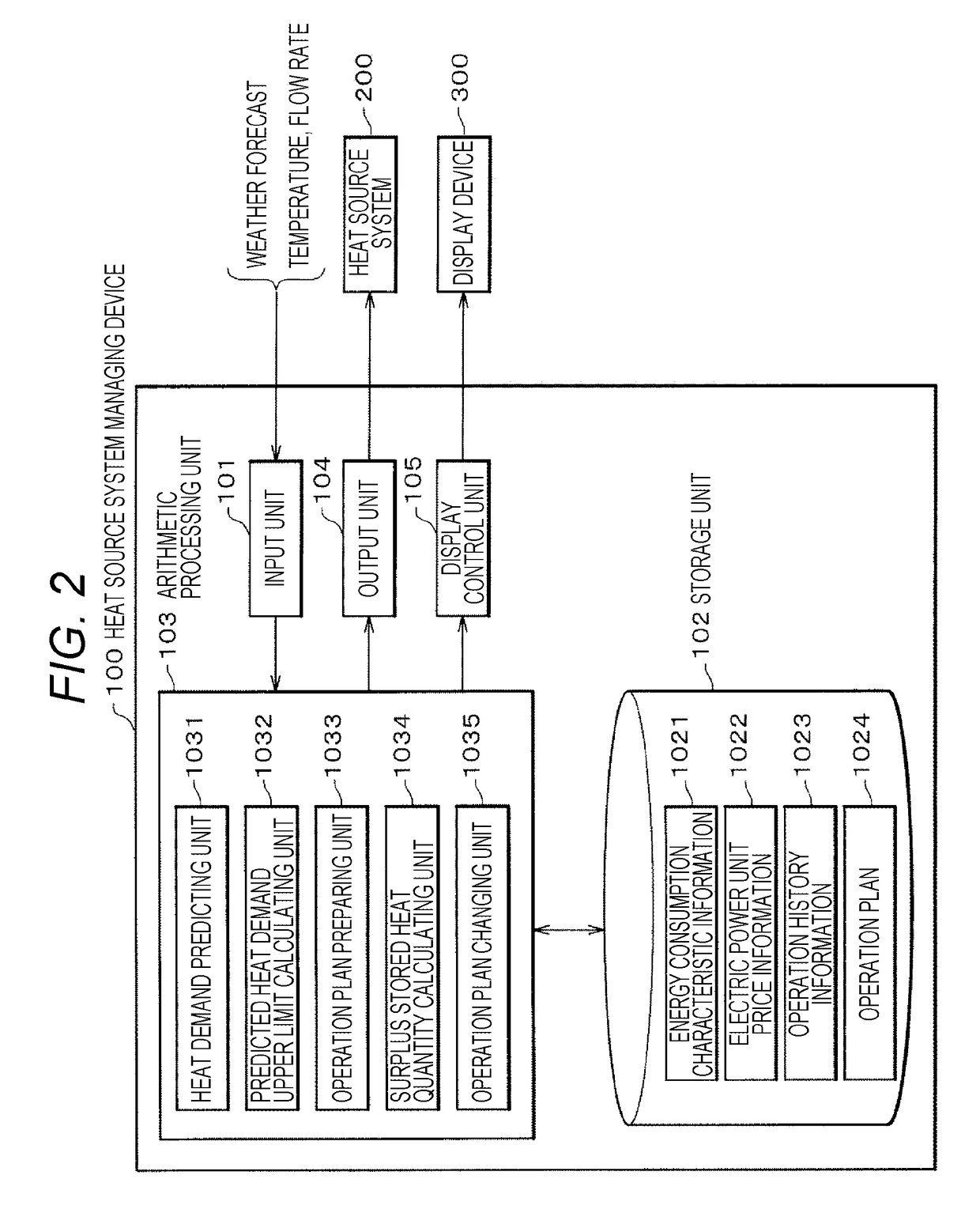
[0018]FIG. 1 is a diagram illustrating a configuration including a heat source system managing device 100 according to an embodiment of the invention. Solid arrows in FIG. 1 indicate directions of cold water flowing in pipes, and dotted arrows indicate signal lines. Hereinafter, a heat source system 200 which is a management target of the heat source system managing device 100 will be first described and then the heat source system managing device 100 will be described in detail.

[0019]The heat source system 200 is a system that supplies cold heat to water which is a “heat medium” using a refrigerator 211a and the like and supplies the cold heat to a consuming facility F (such as a building or a plant) via a heat storage tank 213. The heat source system 200 includes a primary system 210 that generates cold heat and stores the generated cold heat in the heat storage tank 213 and a secondary system 220 that consumes the cold heat stored in the heat storage tank 213.

(Primary System)

[002...

modified example

[0110]While the heat source system managing device 100 according to the invention has been described in conjunction with the embodiment, the invention is not limited to the description but can be modified in various forms.

[0111]For example, when changing the operation plan using the operation plan changing unit 1035 (S109 in FIG. 4), the heat source system managing device 100 may adjust the number of refrigerators 211a and the like operating such that the residual stored heat quantity of the heat storage tank 213 is not less than a “residual stored heat quantity lower limit.”

[0112]The “residual stored heat quantity lower limit” is a lower limit of the residual stored heat quantity for supplying heat of the predicted heat demand upper limit to the consuming facility F and varies with the lapse of time. Specifically, after the current time (for example, 10:00), the cold heat quantity corresponding to the area surrounded with the curve of the predicted heat demand upper limit and the c...


PUM


Abstract

A heat source system managing device includes: a predicted heat demand upper limit calculating unit configured to calculate a predicted heat demand upper limit by adding a prediction error to a predicted heat demand value for a heat source system; an operation plan preparing unit configured to prepare an operation plan of the heat source system to supply heat of the predicted heat demand upper limit to a consuming facility; a surplus stored heat quantity calculating unit configured to repeatedly perform a process of calculating a surplus stored heat quantity by subtracting a heat quantity consumed by the consuming facility from the predicted heat demand upper limit; and an operation plan changing unit configured to sequentially change the operation plan by decreasing a future operation rate of a refrigerator to cancel the surplus stored heat quantity.

Description

TECHNICAL FIELD[0001]The present invention relates to a heat source system managing device that manages a heat source system, and the like.BACKGROUND ART[0002]Recently, prevention of global warming has attracted more attention and there is demand for a decrease in emission of CO2 or energy saving. In this regard, in the manufacturing industries, energy saving by reformation of manufacturing processes, introduction of high-efficiency energy saving devices, fuel switching, and the like has been actively tried with the oil crisis as a trigger and thus energy consumption is substantially kept unchanged.[0003]On the other hand, in sectors of housing and business, with spread of life styles in which comfort or convenience is pursued, energy consumption has increased yearly. In the future, there is demand for an increase in efficiency of a heat source system that supplies thermal energy to consuming facilities such as buildings or plants to achieve more energy saving. For example, the foll...

Claims


Application Information

Patent Timeline
IPC IPC(8): F24D11/00F24D19/10F24F11/00F28D19/00F24F11/02
CPCF24D11/004F24F11/0012F24F2011/0058F24F11/02F24D19/1006F28D19/00F28D20/0034F24F2140/60F24F11/47F24F11/89F24F2130/10F24F11/30F24F2110/10Y02E60/14F24F11/46F24F11/64F24F2140/00F24F2130/00
Inventor KAWAMURA, TSUTOMUKAWABATA, KAORUNAKAMURA, RYOUSUKEKIKUCHI, HIROSHIGEIKEDA, SUSUMU
Owner HITACHI LTD
Why Eureka
Try Eureka