
Ice maker with freezing aid

a technology of ice maker and ice maker, which is applied in the field of ice maker, can solve the problems of inconvenient use and significant acceleration of ice production, and achieve the effect of accelerating ice production

Inactive Publication Date: 2017-11-02
EMZ HANAUER
View PDF13 Cites 0 Cited by
  • Summary
  • Abstract
  • Description
  • Claims
  • Application Information

AI Technical Summary

Benefits of technology

The patent describes a solution for improving the speed of ice formation in an ice-making tray. The solution involves using a heat-dissipating structure with heat-dissipating pins that are in contact with the water in the tray. The heat-dissipating pins absorb heat from the water and transfer it to the air of the first air channel, where it is used to cool the ice-piece-producing cavities. This increases the heat transfer and accelerates the freezing process. The heat-dissipating pins can be positioned in the ice-piece-producing cavities, and a pin-release device can be used to release the pins from the ice pieces. This prevents the ice pieces from sticking together and allows for easy detachment. In some embodiments, a second air channel is provided beneath the ice-making tray to further enhance ice production.

Problems solved by technology

The repeated manual filling of an ice-making tray with water and placing of the tray in a freezing compartment of the refrigerator is generally perceived as being inconvenient by users.
There are doubts as to whether, in the case of an ice-making tray which is to be operated manually by the user, that is to say manually filled with water and then placed in a freezing compartment of a refrigerator, the mere provision of metal parts which establish a heat-conducting connection between the inside of an ice-piece-producing cavity and the outside leads to a significant acceleration in ice production.

Method used


Image

  • Ice maker with freezing aid
  • Ice maker with freezing aid
  • Ice maker with freezing aid

Examples


Embodiment Construction

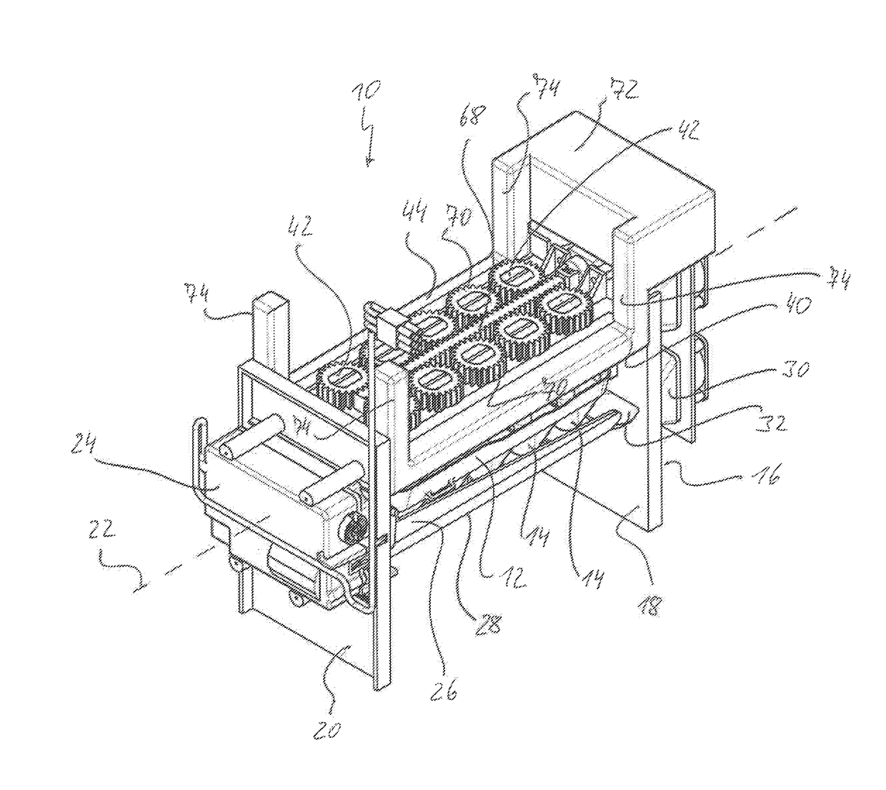
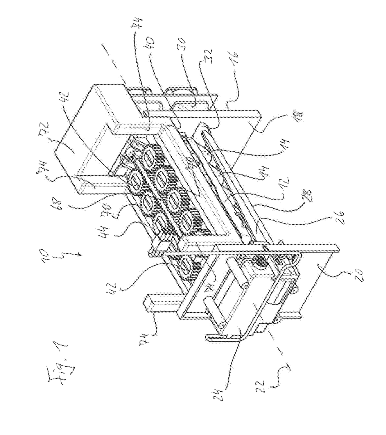
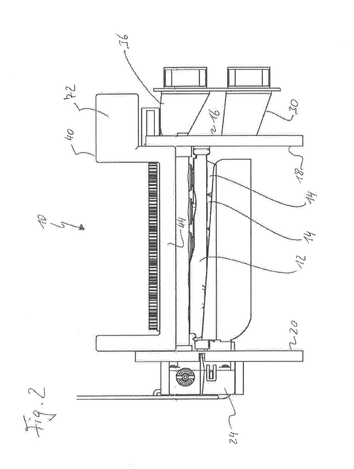
[0036]Reference is first made to FIGS. 1 and 2. The ice maker shown therein is generally designated 10. It comprises as the central component an ice-making tray 12 which serves to produce ice pieces. The ice-making tray 12 forms a plurality of ice-piece-producing cavities 14 which can be filled with fresh water by means of a water supply device (not shown). By the action of cold, the water in the ice-piece-producing cavities 14 freezes. The ice maker 10 works by the so-called twisted tray principle, according to which the ice-making tray 12 is twisted in order to release the frozen ice pieces from the cavity walls of the ice-piece-producing cavities 14. In an ice-ejecting rotational position of the ice-making tray 12, the finished ice pieces are then able to fall out of the ice-making tray 12 and be caught in a collecting container (not shown) situated beneath the ice maker 10.

[0037]The ice maker 10 comprises a base frame 16, which in the example shown comprises two frame plates 18,...


PUM


Abstract

An ice maker for fitting into a cooling or freezing appliance includes an ice-making tray which forms a plurality of ice-piece-producing cavities for producing one ice piece each. An air channel is formed above the ice-making tray, which serves to guide a cold air stream. There is provided a heat-dissipating structure including a metal material and having a plurality of heat-dissipating pins, each of which, in a freezing phase, projects from above, with a pin tip leading, into one of the ice-piece-producing cavities. In some embodiments, the heat-dissipating pins extend into and through the upper air channel, so that the cold air flowing in the air channel flows around shaft portions of the heat-dissipating pins situated inside the air channel. When the ice-piece-producing cavities are filled with water, the heat-dissipating pins immersed in the water ensure improved dissipation of thermal energy from the water, which accelerates freezing.

Description

BACKGROUND OF THE INVENTION1. Field of the Invention[0001]The present invention relates generally to an ice maker for fitting into a cooling or freezing appliance for domestic use.2. Description of the Prior Art[0002]Refrigerators for the domestic sector are nowadays frequently demanded that have an ice maker which allows ice pieces, for example in the form of ice cubes, to be produced automatically. The repeated manual filling of an ice-making tray with water and placing of the tray in a freezing compartment of the refrigerator is generally perceived as being inconvenient by users. Automatic ice makers automatically perform the functions of filling an ice-making tray with water and emptying the tray as soon as the water has frozen into ice pieces, without the involvement of the user.[0003]In ice making, a high production rate is generally desired, that is to say the freezing process is to be kept as short as possible so that all the more ice pieces can be produced in a given period...

Claims


Application Information

Patent Timeline
Patent Type & Authority Applications(United States)
IPC IPC(8): F25C1/24F25C5/08
CPCF25C1/24F25C2305/022F25C5/08F25C1/08F25C5/06F25C2500/02F25C5/22F25C2305/0221
Inventor DIRNBERGER, ALBERT
Owner EMZ HANAUER
Learn More