Ice making system and air flow circulation for slimline ice compartment

a slimline ice and air flow technology, applied in the field of compact ice making system and air flow circulation for use in slimline ice compartments, can solve the problems of less desirable to customers/users, less volume, ergonomically optimal for customers/users, etc., to achieve less volume, reduce ice contamination, and speed up ice production

Active Publication Date: 2019-11-05
BSH HOME APPLIANCES CORP +1
View PDF15 Cites 0 Cited by
  • Summary
  • Abstract
  • Description
  • Claims
  • Application Information

AI Technical Summary

Benefits of technology

[0004]An apparatus consistent with the present disclosure is directed to a self-contained, dedicated compartment for producing and storing ice, without using cold air that is produced outside of the ice compartment and then ducted to and from the ice compartment. This in turn minimizes any ice contamination by air that has moved from another compartment and makes the ice compartment less dependent on the freezer compartment states or temperatures.
[0005]An apparatus consistent with the present disclosure is directed to a slimline ice compartment which takes up less volume in the fresh food compartment and results in faster ice production.
[0006]An apparatus consistent with the present disclosure results in a significant reduction of the internal volume that the ice compartment takes up inside the fresh food compartment, as it combines an ice tray and an evaporator into a single piece with the bottom of the ice maker (a metallic tray portion) also acting as an evaporator for the ice compartment. This in turn eliminates the need for an additional evaporator to cool the air inside the insulated ice compartment.
[0007]An apparatus consistent with the present disclosure results in a much higher ice production, as the evaporator cooling tube is in direct contact with the ice maker tray portion of the ice maker tray / evaporator, and this in turn reduces the time to fill the ice bucket. In particular, the ice maker tray / evaporator of the present disclosure freezes the water in the mold cavities very fast, since the ice maker tray portion temperature runs as cold as the refrigerant is evaporated.
[0008]An apparatus consistent with the present disclosure results in a configuration where the air flow is pulled or sucked under the ice maker tray portion of the ice maker assembly thereby to maximize the heat transfer. Moreover, having the air return closer to a front portion of the ice bucket (warmest area) allows the evaporator fins of the ice maker tray / evaporator to be designed with optimum spacing to prevent ice accumulation that could choke the air flow under the ice maker tray / evaporator and cause temperatures inside the ice compartment to rise.
[0010]According to one aspect, the present disclosure provides a refrigerator including a refrigerator compartment; a freezer compartment; an ice compartment disposed in the refrigerator compartment; an ice maker assembly disposed in the ice compartment, the ice maker assembly including an ice maker tray / evaporator having an evaporator cooling tube which is in direct contact with the ice maker tray portion; an ice bucket for storing ice disposed in the ice compartment; and an air handler / auger motor assembly disposed at a rear portion of the ice compartment behind the ice bucket. The air handler / auger motor assembly includes an air passage having a fan disposed therein. An inlet of the fan communicates with an airflow passage under the ice maker tray / evaporator, such that the fan creates a suction and draws cool air from the ice maker tray / evaporator and discharges the cool air through the air passage and to the ice bucket to prevent any ice in the ice bucket from melting.

Problems solved by technology

On the other hand, making the ice compartment and bucket larger especially in the vertical height direction takes up too much volume in the fresh food compartment, thereby making it less desirable to customers / users.
Making the ice compartment taller also limits a design to be used only on taller doors (for example, it would not be useable in models with more than 1 drawer and two doors), and / or require the ice and water dispenser to be positioned at a lower position which is not ergonomically optimum for customers / users.

Method used


Image

  • Ice making system and air flow circulation for slimline ice compartment
  • Ice making system and air flow circulation for slimline ice compartment
  • Ice making system and air flow circulation for slimline ice compartment

Examples


Embodiment Construction

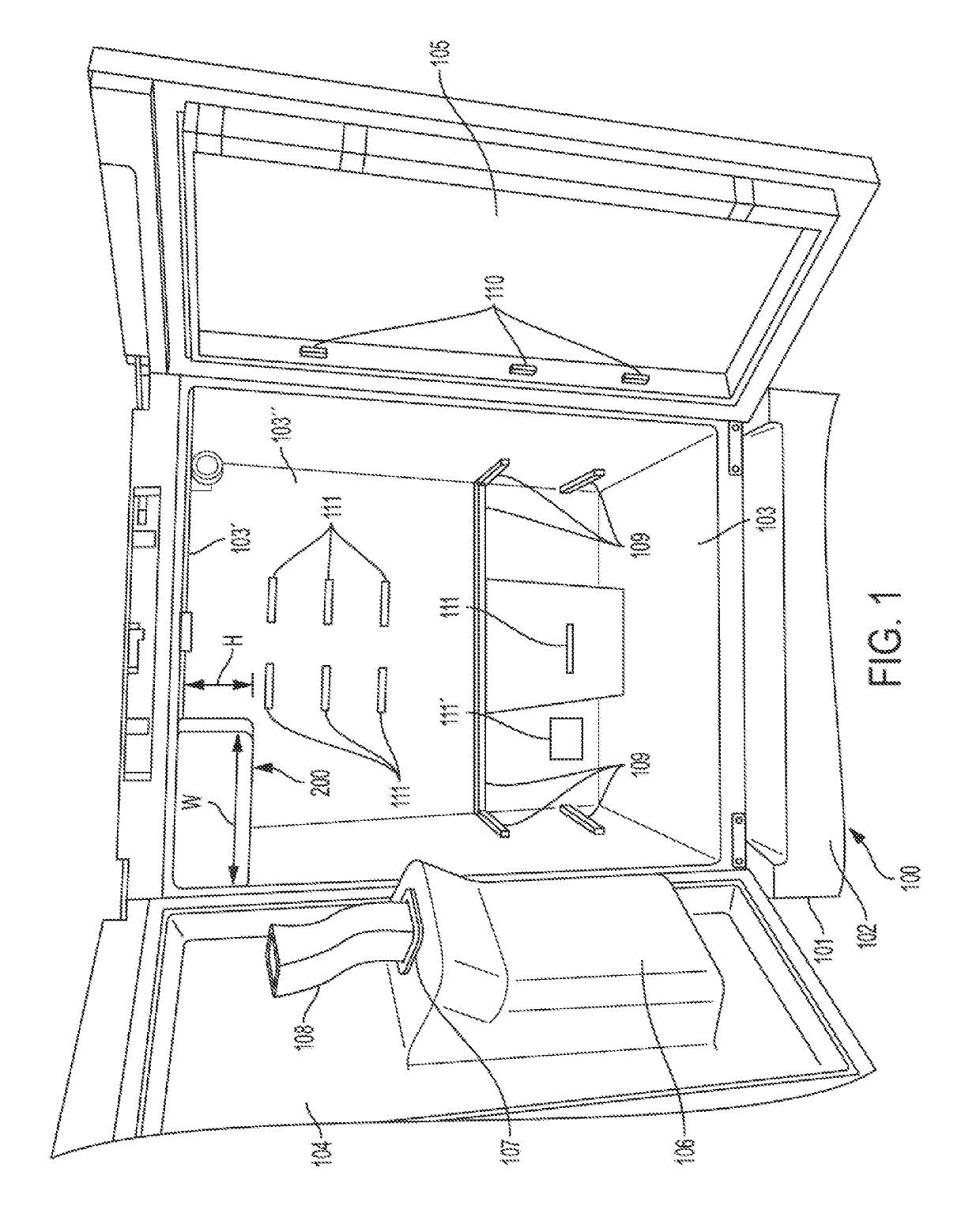
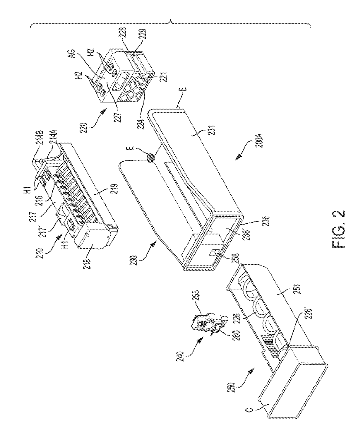
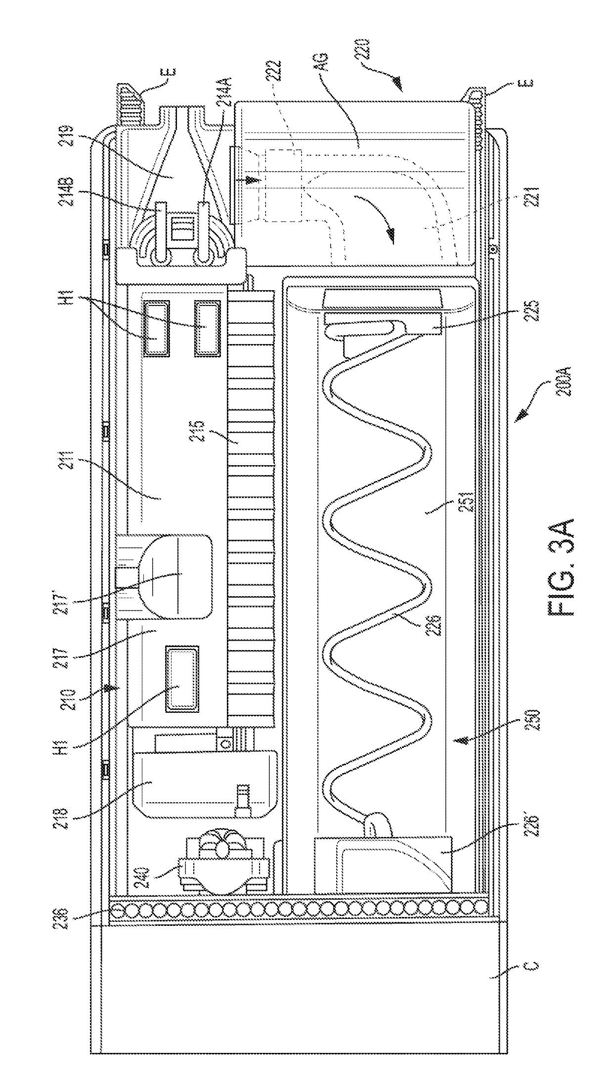
[0047]The exemplary embodiments set forth below represent the necessary information to enable those skilled in the art to practice the invention. Upon reading the following description in light of the accompanying drawing figures, those skilled in the art will understand the concepts of the invention and will recognize applications of these concepts not particularly addressed herein. It should be understood that these concepts and applications fall within the scope of the disclosure and the accompanying claims.

[0048]Moreover, it should be understood that terms such as top, bottom, front, rearward, upper, lower, upward, downward, and the like used herein are for orientation purposes with respect to the drawings when describing the exemplary embodiments and should not limit the present invention. Also, terms such as substantially, approximately, and about are intended to allow for variances to account for manufacturing tolerances, measurement tolerances, or variations from ideal value...


PUM


Abstract

A refrigerator including a refrigerator compartment; a freezer compartment; an ice compartment disposed in the refrigerator compartment; an ice maker assembly disposed in the ice compartment, the ice maker assembly including an ice maker tray / evaporator having an evaporator cooling tube which is in direct contact with the ice maker tray portion; an ice bucket for storing ice disposed in the ice compartment; and an air handler / auger motor assembly disposed at a rear portion of the ice compartment behind the ice bucket. The air handler / auger motor assembly includes an air passage having a fan disposed therein. An inlet of the fan communicates with an airflow passage under the ice maker tray / evaporator, such that the fan creates a suction and draws cool air from the ice maker tray / evaporator and discharges the cool air through the air passage and to the ice bucket to prevent any ice in the ice bucket from melting.

Description

FIELD OF THE INVENTION[0001]The present disclosure relates generally to a refrigerator appliance and to an ice making system disposed in a dedicated ice compartment of the refrigerator appliance. More particularly, the present disclosure relates to a compact ice making system and air flow circulation for use in a slimline ice compartment having a side-by-side ice maker and ice bucket.BACKGROUND OF THE INVENTION[0002]In general, refrigerator appliances, such as for household use, typically have a bulky ice compartment for making and storing ice located within the fresh food compartment. The ice compartment assembly has an over-under arrangement where the ice maker is positioned on top and the ice bucket is located underneath the ice maker within the ice compartment.SUMMARY OF THE INVENTION[0003]On the other hand, making the ice compartment and bucket larger especially in the vertical height direction takes up too much volume in the fresh food compartment, thereby making it less desir...

Claims


Application Information

Patent Timeline
Patent Type & Authority Patents(United States)
IPC IPC(8): F25C1/24F25C5/20F25D17/06F25D23/02
CPCF25C1/24F25D17/065F25C5/22F25D2317/063F25D2317/061F25D2317/0671F25C2400/10F25D2700/122F25D23/02F25D2700/10F25D2317/0665F25C2700/12
Inventor BERTOLINI, NILTONMARQUES, MARCOMONTALVO SANCHEZ, JORGE CARLOSROTONDA, MARCO
Owner BSH HOME APPLIANCES CORP
Why Eureka
Try Eureka