
Compact ice making system for slimline ice compartment

a compact, ice-making technology, applied in the field of compact ice-making systems for slimline ice-making compartments, can solve the problems of occupying too much volume, less desirable to customers/users, ergonomically optimum for customers/users, etc., to achieve the effect of reducing internal volume, less volume, and faster ice-making

Active Publication Date: 2021-03-16
BSH HOME APPLIANCES CORP +1
View PDF22 Cites 0 Cited by
  • Summary
  • Abstract
  • Description
  • Claims
  • Application Information

AI Technical Summary

Benefits of technology

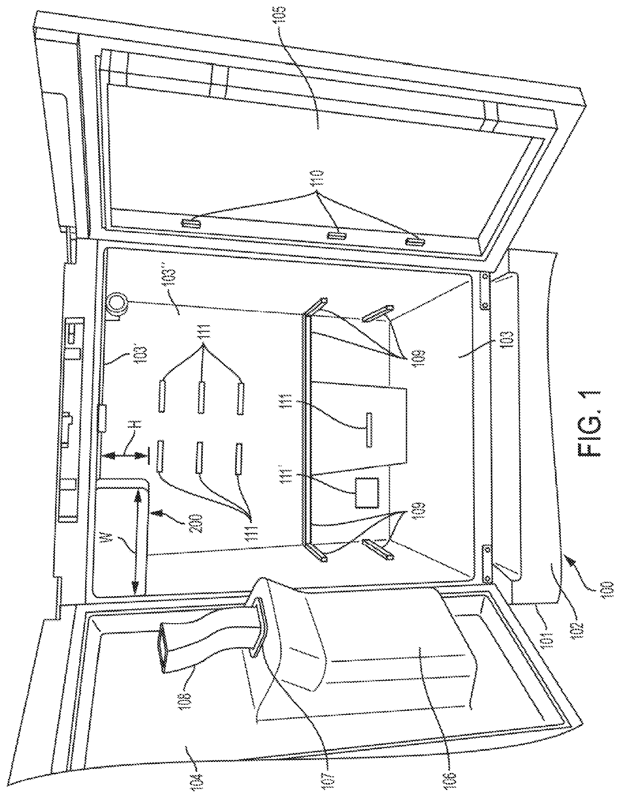
[0006]An apparatus consistent with the present disclosure is directed to a slimline ice compartment which takes up less volume in the fresh food compartment and results in faster ice production.
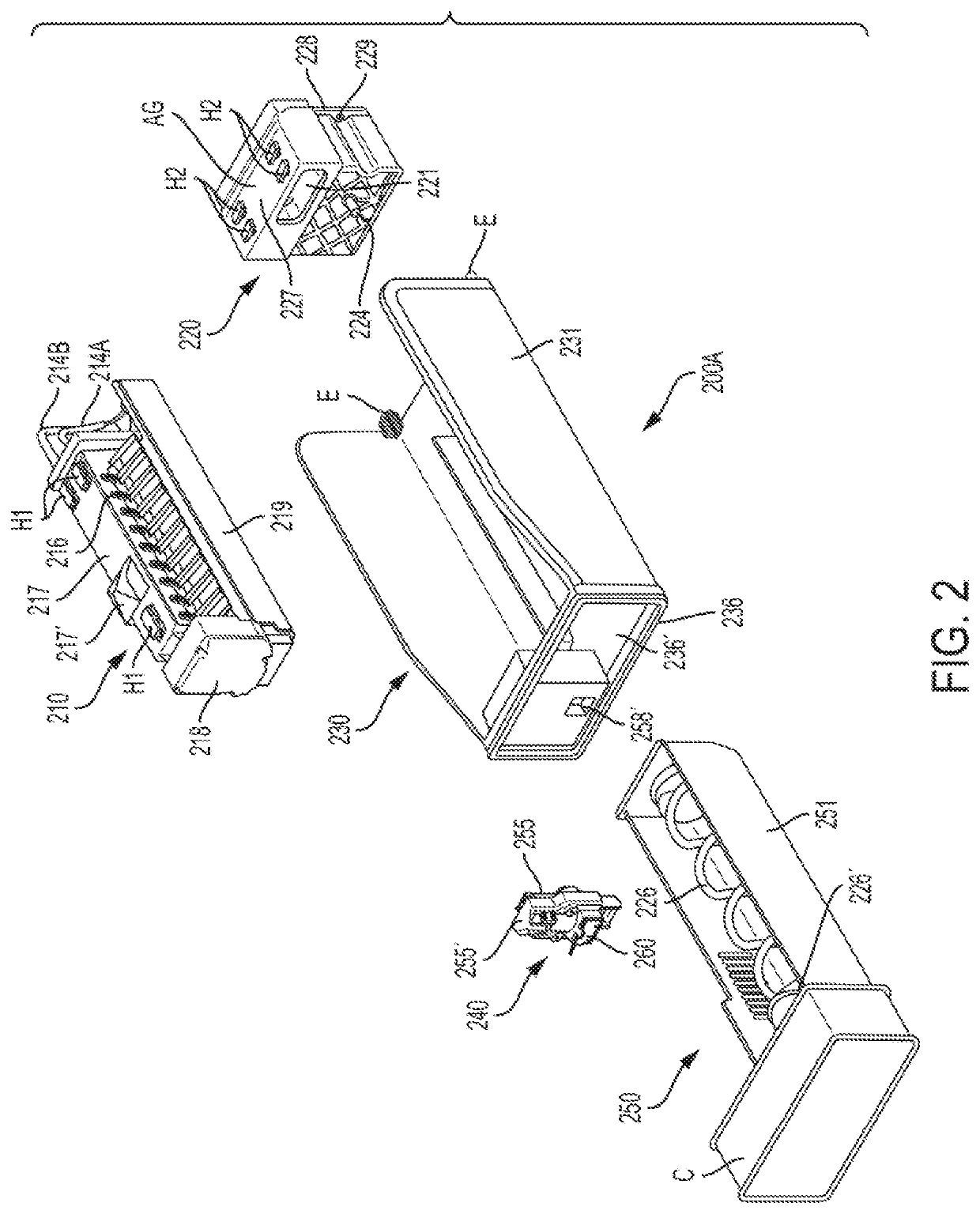
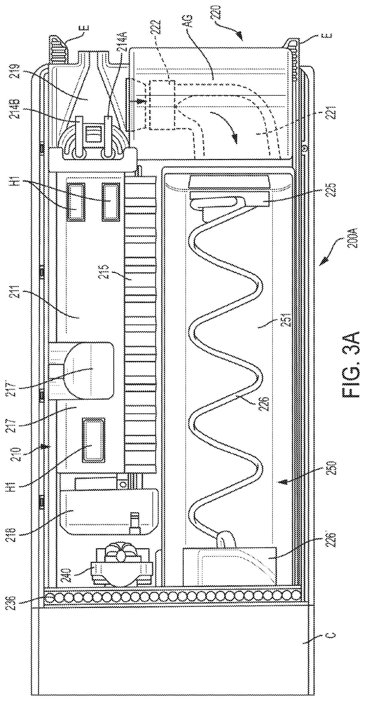
[0007]An apparatus consistent with the present disclosure results in a significant reduction of the internal volume that the ice compartment takes up inside the fresh food compartment, as it combines an ice tray and an evaporator into a single piece with the bottom of the ice maker (a metallic tray portion) also acting as an evaporator for the ice compartment. This in turn eliminates the need for an additional evaporator to cool the air inside the insulated ice compartment.
[0008]An apparatus consistent with the present disclosure results in a much higher ice production, as the evaporator cooling tube is in direct contact with the ice maker tray portion of the ice maker tray / evaporator, and this in turn reduces the time to fill the ice bucket. In particular, the ice maker tray / evaporator of the present disclosure freezes the water in the mold cavities very fast, since the ice maker tray portion temperature runs as cold as the refrigerant is evaporated.
[0024]According to another aspect, the air handler / auger motor assembly comprises an air duct having a motor driven fan disposed therein, wherein an inlet of the motor driven fan communicates with an airflow passage under the ice maker tray / evaporator, such that the motor driven fan creates a suction and draws cool air from the ice maker tray / evaporator and discharges the cool air through the air duct and to the ice bucket to prevent any ice pieces in the ice bucket from melting.

Problems solved by technology

On the other hand, making the ice compartment and bucket larger especially in the vertical height direction takes up too much volume in the fresh food compartment, thereby making it less desirable to customers / users.
Making the ice compartment taller also limits a design to be used only on taller doors (for example, it would not be useable in models with more than 1 drawer and two doors), and / or require the ice and water dispenser to be positioned at a lower position which is not ergonomically optimum for customers / users.

Method used


Image

  • Compact ice making system for slimline ice compartment
  • Compact ice making system for slimline ice compartment
  • Compact ice making system for slimline ice compartment

Examples


first embodiment

[0100]As best shown in FIGS. 15B, 18, and 19A, an ice maker guard 715 is fastened to the side of the integral ice maker assembly unit 712 facing the ice bucket 751. The ice maker guard 715 includes a plurality of projections or fingers 715′. Ejector fingers or plates 716 are arranged on a rotatable shaft 716′ and are movable in spaces between the projections 715′. The rotatable shaft 716′ is supported in an ejector finger bearing 716″. The ice maker bracket 717 is disposed above the mold with a plurality of cavities 712′ and includes a water fill cup 717′ for directing water into the cavities 712′. The ice maker bracket 717 is attached via fasteners (for example, screws) to the integral ice maker assembly unit 712. The ice maker bracket 717 also includes a plurality (for example three) of mounting hooks HH1 on a top surface thereof for engaging corresponding mounting members MM1 assembled directly into an inner top wall 603′ which is part of the refrigerator structure (see FIGS. 20A...

second embodiment

[0102]As best shown in FIGS. 14, 15A, 15B, 18, and 20B, the gear box 718 is positioned at a front end portion (facing the front of the refrigerator) of the integral ice maker assembly unit 712 and includes gears and a motor (not shown) for driving the rotatable shaft 716′ and the bail arm or optical sensor system that senses the amount of ice pieces in the ice bucket 751. In the second embodiment, an optical sensor system, comprising the optical sensor OSE (emitter) that is disposed on the ice maker bracket 717 and the optical sensor OSR (receiver) that is disposed on the gear box 718, is provided for sensing the amount of ice pieces in the ice bucket 751. The receiver OSR is built into the gear box 718, while the emitter OSE has its own housing that is latched on the right rear end of the ice maker bracket 717 (see FIGS. 14, 15A, 15B, 18, and 19C). A temperature or tray sensor such as a thermistor TT is disposed on an outer portion of the gear box 718 facing the integral ice maker ...


PUM


Abstract

A refrigerator including a fresh food compartment; a freezer compartment; an ice compartment disposed in the fresh food compartment; an ice maker disposed in the ice compartment, the ice maker including an ice maker tray, a separate fin evaporator, and a cooling tube which is assembled between the ice maker tray and the fin evaporator, such that the cooling tube is in direct contact with the ice maker tray and the fin evaporator; and an ice bucket for storing ice, the ice bucket being disposed in the ice compartment.

Description

CROSS-REFERENCE TO RELATED APPLICATIONS[0001]The present application is a continuation-in-part of U.S. patent application Ser. No. 15 / 643,601, filed on Jul. 7, 2017, the contents of which are herein incorporated by reference in their entirety.FIELD OF THE INVENTION[0002]The present disclosure relates generally to a refrigerator appliance and to an ice making system disposed in a dedicated ice compartment of the refrigerator appliance. More particularly, the present disclosure relates to a compact ice making system for use in a slimline ice compartment having a side-by-side ice maker and ice bucket.BACKGROUND OF THE INVENTION[0003]In general, refrigerator appliances, such as for household use, typically have a bulky ice compartment for making and storing ice located within the fresh food compartment. The ice compartment assembly has an over-under arrangement where the ice maker is positioned on top and the ice bucket is located underneath the ice maker within the ice compartment.SUMM...

Claims


Application Information

Patent Timeline
Patent Type & Authority Patents(United States)
IPC IPC(8): F25C1/10F25C5/20F25C5/187
CPCF25C1/10F25C5/187F25C5/22F25C2400/00F25D2323/021F25C2500/02
Inventor BERTOLINI, NILTONGÖRZ, ALEXANDERMONTALVO SANCHEZ, JORGE CARLOSVEKARIYA, VISHAL
Owner BSH HOME APPLIANCES CORP
Learn More