
Vehicle accident management system and method for operating same

a technology for accident management and vehicles, applied in traffic control systems, instruments, greenhouse gas reduction, etc., can solve problems such as social loss and inability to provide information reflecting actual situation, and achieve the effect of preventing a secondary acciden

Inactive Publication Date: 2017-11-02
YUN SUK JU
View PDF23 Cites 11 Cited by
  • Summary
  • Abstract
  • Description
  • Claims
  • Application Information

AI Technical Summary

Benefits of technology

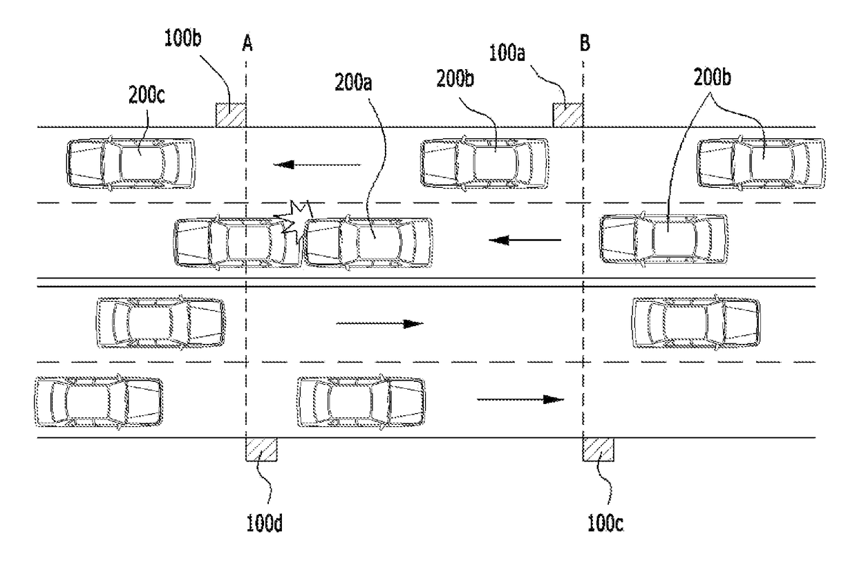
The present invention aims to provide a system for managing accidents in vehicles. The system can notify neighboring vehicles of a sudden change in the forward driving environment, allowing them to detect a dangerous situation and prevent a secondary accident. Additionally, the system can share information about the accident in real-time and provide necessary information to drivers in a timely manner, ensuring smooth traffic flow. Furthermore, the system can only transmit risk detection signals to vehicles with a direction identical to that of the involved vehicle, ensuring only appropriate drivers become aware of the risk and use it for safe driving.

Problems solved by technology

A conventional anti-lock braking system installed in a vehicle, a conventional electronic driving safety device installed in a vehicle, or a conventional voice recognition function configured to prevent a driver from becoming drowsy or negligent while driving is provided only to a vehicle or user that employs a specific service or platform, thereby being unable to provide information reflecting an actual situation.
In Korea, traffic accidents attributable to fog or sea fog generated on a bridge or a road close to the sea occur frequently due to geographical characteristics, and the accidents often lead to serial rear-end collision accidents, thereby causing considerable social loss.

Method used


Image

  • Vehicle accident management system and method for operating same
  • Vehicle accident management system and method for operating same
  • Vehicle accident management system and method for operating same

Examples


Embodiment Construction

[0017]The above-described objects, features, and advantages will be described in detail below with reference to the accompanying drawings. Accordingly, those having ordinary knowledge in the art to which the present invention pertains will easily practice the technical spirit of the present invention. In the description of the present invention, in the case in which it is determined that a detailed description of a well-known technology associated with the present invention may unnecessarily make the gist of the present invention unclear, it will be omitted. Preferred embodiments of the present invention will be described in detail below with reference to the accompanying drawings. Throughout the drawings, the same reference symbols designate the same components or similar components.

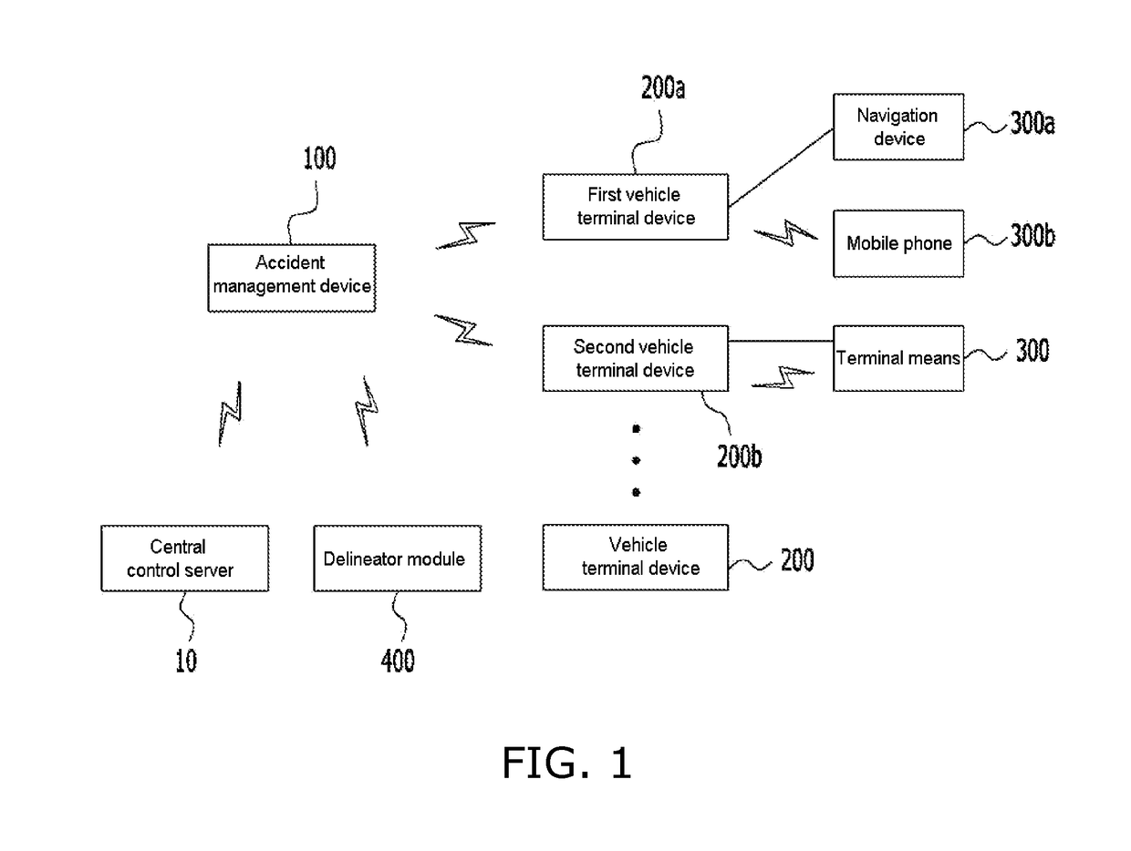
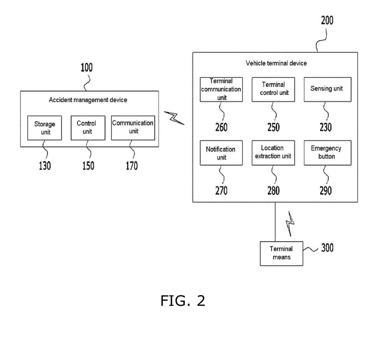
[0018]The configuration and exemplary operation of a vehicle accident management system according to embodiments of the present invention will be described below with reference to FIG. 1 to FIG. 3.

[0019...


PUM


Abstract

Disclosed herein are a vehicle accident management system and a method for operating the same. The method for operating a vehicle accident management system including vehicles configured such that respective vehicle terminal devices are attached thereto and an accident management device installed on a roadside includes: transmitting, by a first vehicle terminal device, accident and location information to the accident management device when a vehicle abnormality detection signal or a risk signal attributable to user operation is generated; receiving, by the accident management device, the information; searching, by the accident management device, for a second vehicle terminal device having a moving direction identical to that of the first vehicle terminal device and located within a preset distance behind the first vehicle terminal device; and transmitting, by the accident management device, the information to the second vehicle terminal device based on the result of the search.

Description

BACKGROUND1. Technical Field[0001]The present invention relates to a vehicle accident management system and a method for operating the same. More specifically, the present invention relates to a vehicle accident management system including vehicles configured such that respective vehicle terminal devices are attached thereto and an accident management device installed on a roadside, and also relates to a method for operating the vehicle accident management system.2. Description of the Related Art[0002]A conventional anti-lock braking system installed in a vehicle, a conventional electronic driving safety device installed in a vehicle, or a conventional voice recognition function configured to prevent a driver from becoming drowsy or negligent while driving is provided only to a vehicle or user that employs a specific service or platform, thereby being unable to provide information reflecting an actual situation.[0003]Accordingly, there is a need for a technology capable of enabling ...

Claims


Application Information

Patent Timeline
Patent Type & Authority Applications(United States)
IPC IPC(8): G08G1/01G08G1/0965G08G1/16G08G1/0967G01S19/13
CPCG08G1/0112G08G1/096775G01S19/13G08G1/164G08G1/0965G08G1/095G08G1/096716G08G1/096741G08G1/096783G08G1/162Y02E10/50Y02E70/30H02S40/38H04W4/80G01W1/06G06Q50/10H01L31/042H04W4/025G06Q50/40
Inventor YUN, SUK JU
Owner YUN SUK JU
Learn More