
Emergency alert and warning apparatus

a technology of emergency alert and warning apparatus, applied in the direction of instruments, greenhouse gas reduction, roads, etc., can solve the problems of driver's limit on identifying the reflector, exposure to accidents, loss of life, etc., and achieve the effect of preventing a secondary accident and preventing a major traffic acciden

Active Publication Date: 2018-10-04
ETL
View PDF0 Cites 6 Cited by
  • Summary
  • Abstract
  • Description
  • Claims
  • Application Information

AI Technical Summary

Benefits of technology

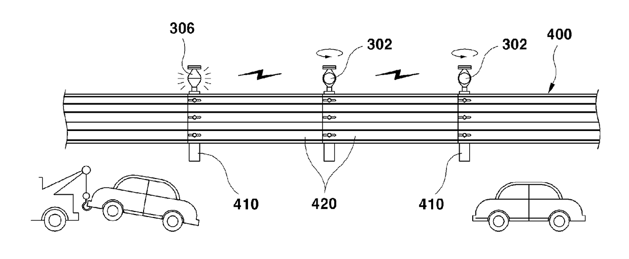
The present invention is about an emergency alert and warning system that is placed in the middle of an expressway or other road to alert drivers to an emergency situation, such as a traffic accident, using both sound and light signals. This system helps drivers slow down and prevents secondary accidents, which can lead to major traffic accidents.

Problems solved by technology

However, it is difficult to install the safety tripod due to vehicles that moves at a high speed in an expressway or a motorway, and there is a risk of exposure to accidents while moving from the vehicle about 100 to 200 meters backward, particularly at night.
In other words, when an accident occurs on an expressway or the like, the following vehicle driver is informed of the accident situation by a cumbersome and dangerous method in which the safety tripod should be set about 100 to 200 meters behind the accident vehicle while turning on the emergency light.
While the emergency light is turned on and the tripod is set about 100 to 200 meters behind the accident vehicle, dozens of vehicles are moving at high speed, which can lead to a more dangerous situation, and accidents that lead to loss of life due to vehicles coming from behind while taking these measures also often happen.
However, it is problematic in that the driver has a limit on identifying the reflector at night.

Method used


Image

  • Emergency alert and warning apparatus
  • Emergency alert and warning apparatus
  • Emergency alert and warning apparatus

Examples


Embodiment Construction

[0037]Hereinbelow, configurations and operation of exemplary embodiments of the present invention will be described in detail with reference to the accompanying drawings.

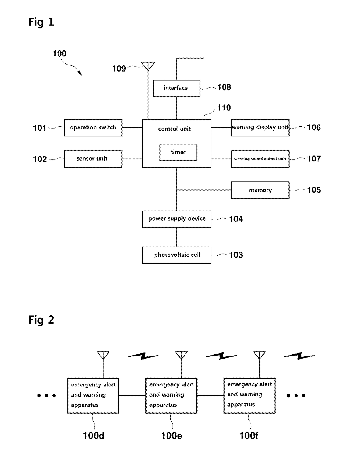
[0038]FIG. 1 is a block diagram showing a configuration of an emergency alert and warning apparatus according to an embodiment of the present invention.

[0039]As shown in FIG. 1, an emergency alert and warning apparatus 100 includes an operation switch 101, a sensor unit 102, a photovoltaic cell 103, a power supply device 104, a memory 105, a warning display unit 106, a warning sound output unit 107, an interface 108, an antenna 109, and a control unit 110.

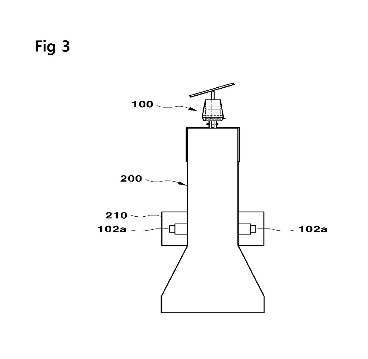
[0040]The emergency alert and warning apparatus 100 is provided in a median strip or a guide rail of an expressway or the like, and each is assigned a unique ID.

[0041]The operation switch 101 generates an operation signal by the user's operation and outputs the same to the control unit 110. The user can be a driver or a passenger of the vehicle which had an acciden...


PUM


Abstract

The present invention relates to an emergency alert and warning apparatus and, more particularly, to a road emergency alert and warning apparatus which is installed on a median strip or a guide rail of an expressway or the like to alert a driver of a rear vehicle of an emergency situation when a traffic accident occurs during nighttime driving, thereby preventing an additional secondary accident. According to an embodiment of the present invention, the emergency alert and warning apparatus comprises: an operation switch which is installed on a median strip or a guide rail of a road to allow a user to generate an operation signal when a traffic accident occurs; a control unit which receives the operation signal to output a control signal, and transmits or relays traffic accident notification data to another neighboring emergency alert and warning apparatus through a wired or wireless communication; a warning display unit which is installed rearward with respect to a traveling direction of a vehicle and includes a plurality of LEDs that are turned on and off in response to the control signal of the control unit; and a photovoltaic cell which converts solar energy into electric energy, processes the electric energy into a constant voltage through a DC / DC converter, and supplies power.

Description

TECHNICAL FIELD[0001]The present invention relates generally to an emergency alert and warning apparatus. More particularly, the present invention relates to an emergency alert and warning apparatus provided on a median strip or a guide rail of an expressway or the like to alert a following vehicle driver to an emergency situation when a traffic accident occurs during nighttime driving, thereby preventing a secondary accident.BACKGROUND ART[0002]Generally, a shoulder refers to both edges of a highway or a motorway, and is used as a stopping space in an emergency of a vehicle or as a moving path of an emergency vehicle.[0003]Accordingly, most of the vehicle drivers stop at the shoulder to solve a problem when the problem such as an abnormality occurs in the vehicle while driving or when an accident occurs.[0004]Here, the vehicle driver sets a safety tripod about 100 to 200 meters behind the vehicle to prevent an additional accident by warning vehicles in motion that the vehicle is st...

Claims


Application Information

Patent Timeline
IPC IPC(8): G08G1/095G08B5/38G08B3/10G08B25/10H02S99/00H02S40/38
CPCG08G1/095G08B5/38G08B3/10G08B25/10H02S99/00H02S40/38G08G1/16E01F15/0438E01F15/08Y02E10/50Y02E70/30
Inventor HONG, YUNG KEUN
Owner ETL
Learn More