
Anisotropic electrically conductive film

an electrically conductive film, anisotropic technology, applied in the direction of line/current collector details, semiconductor devices, semiconductor/solid-state device details, etc., can solve the problems of short circuits between, and achieve the effect of satisfying initial conductivity and conduction reliability, suppressing short circuits, and suppressing short circuits

Active Publication Date: 2017-11-02
DEXERIALS CORP
View PDF2 Cites 7 Cited by
  • Summary
  • Abstract
  • Description
  • Claims
  • Application Information

AI Technical Summary

Benefits of technology

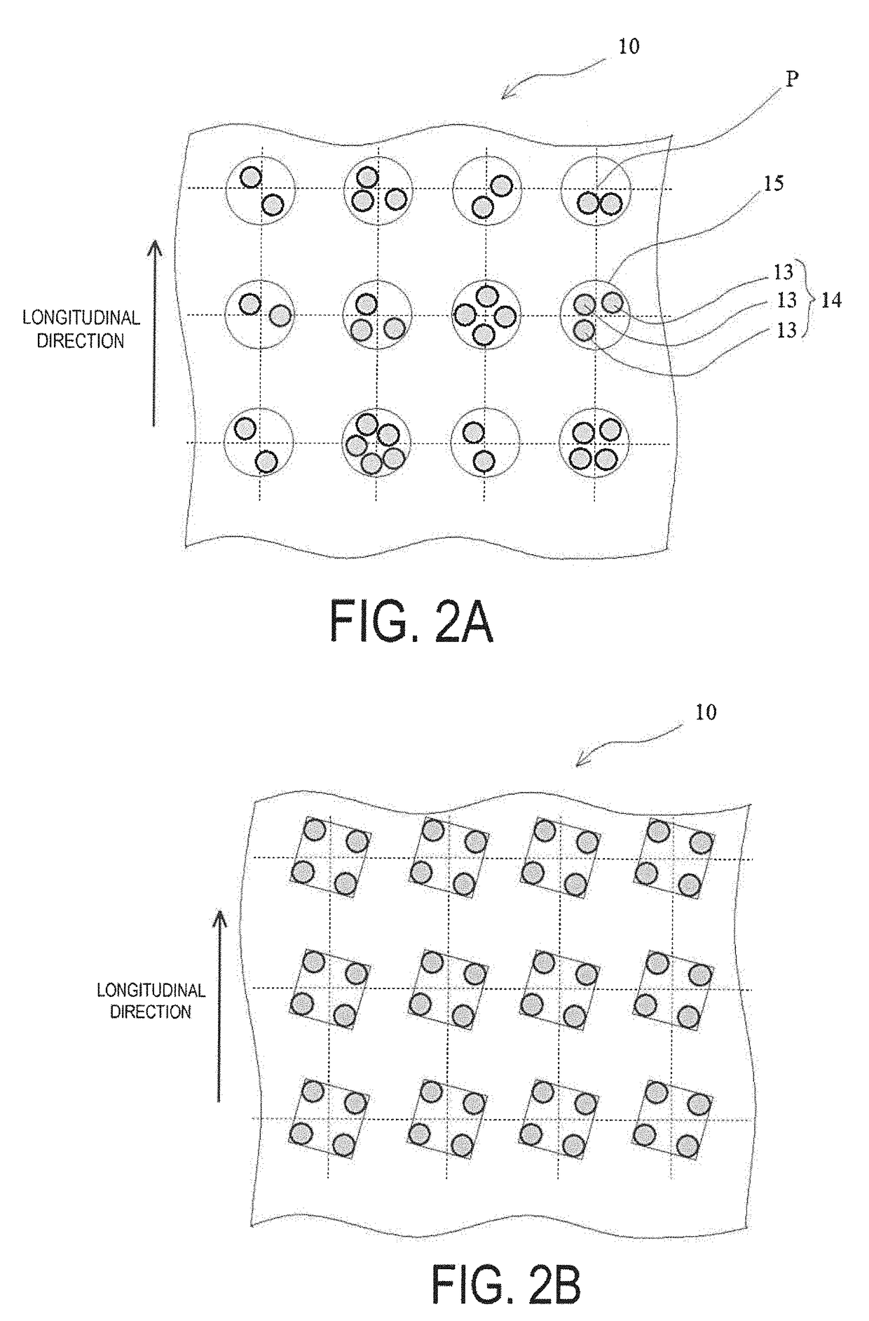
The present invention is related to an anisotropic electrically conductive film used for an anisotropic electrically conductive connection. The film has good initial conductivity and reliable conduction after aging, and it helps prevent short circuits. The production method involves using a transfer body with a convex surface and slightly adhesive portions where conductive particles are deposited and transferred to an insulating adhesive base layer. The resulting film has a pattern of electrically conductive particle groups arranged in a lattice point region. Overall, this film and the method of producing it offer better performance and reliability in anisotropic electrically conductive connections.

Problems solved by technology

Therefore, in the case where the anisotropic electrically conductive film is applied to the connection between the terminals of the wiring board and the terminals of the IC chip having narrowed pitches upon miniaturizing and reducing the weight of electronic devices, a short circuit may occur between the adjacent terminals due to the electrically conductive particles present in a state of being connected or aggregated in the anisotropic electrically conductive film.

Method used


Image

  • Anisotropic electrically conductive film
  • Anisotropic electrically conductive film
  • Anisotropic electrically conductive film

Examples


example 1

[0097]A 2 mm thick nickel plate was prepared. A cylindrically-shaped concave portion (an inner diameter 8 μm and a maximum depth 8 μm) was formed in a tetragonal lattice pattern, and linear grooves having a depth of 1 μm and a width of 1 μm were randomly formed at the bottom (the total area of the grooves was within 70% of the total bottom area). Thus, the transfer body master was obtained. The distance between adjacent concave portions was 12 μm. Accordingly, the density of the concave portions was 2500 / mm2. The inner diameter of the concave portion and the distance between the adjacent concave portions correspond to a convex portion diameter of the transfer body and the shortest distance between the adjacent convex portions.

[0098]The resultant transfer body master was coated with a photopolymerizable resin composition containing 60 parts by mass of phenoxy resin (YP-50, Nippon Steel & Sumikin Chemical Co., Ltd.), 29 parts by mass of acrylate resin (M208, Toagosei Co., Ltd.), and 2...

example 2

[0104]The anisotropic electrically conductive film was obtained by repeating the Example 1 except for changing the distance between the adjacent concave portions to 8 μm when preparing the transfer body master. Note that the density of the concave portions of the transfer body master was 3900 / mm2.

example 3

[0105]The anisotropic electrically conductive film was obtained by repeating the Example 1 except for changing the inner diameter of the concave portion to 12 μm and the distance between the adjacent concave portions to 8 μm when preparing the transfer body master. Note that the density of the concave portions of the transfer body master was 2500 / mm2.


PUM


Abstract

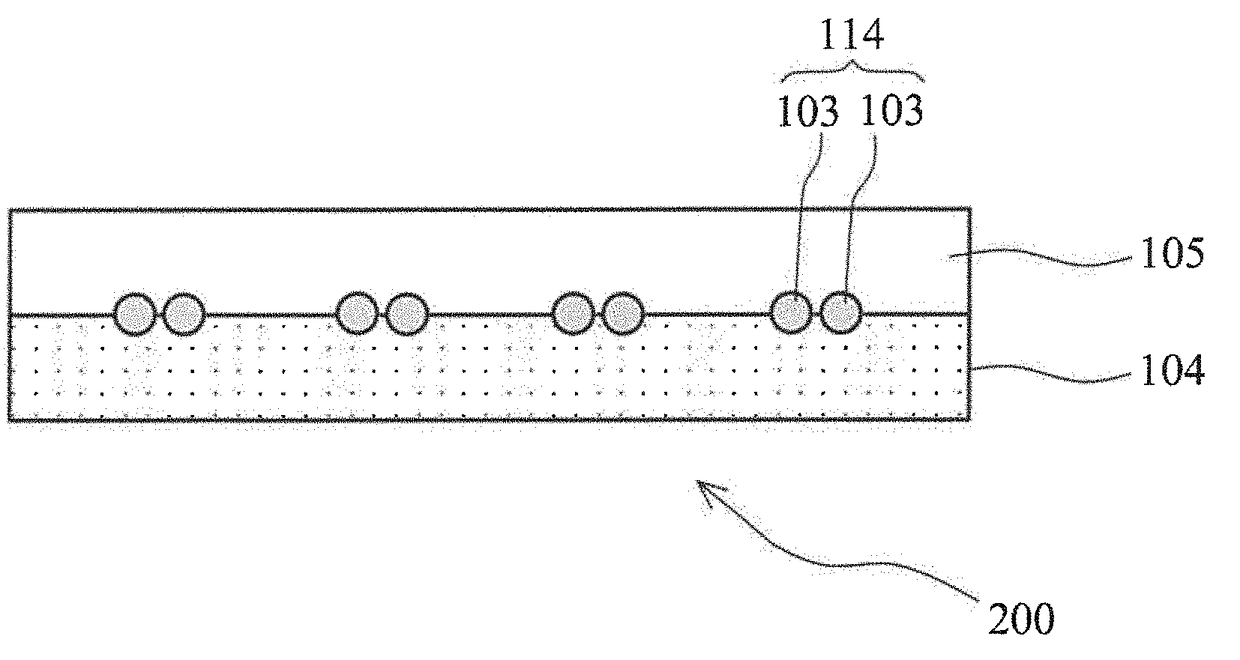
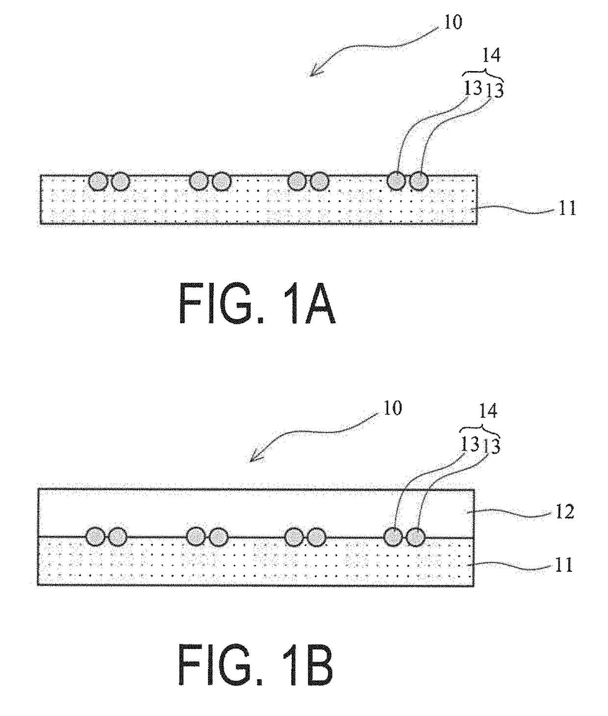
An anisotropic electrically conductive film has a structure wherein the electrically conductive particles are disposed on or near the surface of an electrically insulating adhesive base layer, or a structure wherein an electrically insulating adhesive base layer and an electrically insulating adhesive cover layer are laminated together and the electrically conductive particles are disposed near the interface therebetween. Electrically conductive particle groups configured from two or more electrically conductive particles are disposed in a lattice point region of a planar lattice pattern. A preferred lattice point region is a circle centered on a lattice point. A radius of the circle is not less than two times and not more than seven times the average particle diameter of the electrically conductive particles.

Description

TECHNICAL FIELD[0001]The present invention relates to an anisotropic electrically conductive film.BACKGROUND ART[0002]An anisotropic electrically conductive film having electrically conductive particles dispersed in an electrically insulating resin binder is widely used for mounting electronic components such as IC chips on a wiring board and the like. However, in such an anisotropic electrically conductive film, it is known that the electrically conductive particles are present in a state of being connected or aggregated with each other. Therefore, in the case where the anisotropic electrically conductive film is applied to the connection between the terminals of the wiring board and the terminals of the IC chip having narrowed pitches upon miniaturizing and reducing the weight of electronic devices, a short circuit may occur between the adjacent terminals due to the electrically conductive particles present in a state of being connected or aggregated in the anisotropic electricall...

Claims


Application Information

Patent Timeline
IPC IPC(8): H01L23/00
CPCH01L24/32H01L24/83H01L2224/32225H01L2224/83851H01L2224/29499H01L2224/83203H01L2224/29082H01L24/29H01R11/01H01R43/00
Inventor AKUTSU, YASUSHI
Owner DEXERIALS CORP
Learn More