Multiple implant constructions and fixation methods associated therewith

a multi-implant construction and implant technology, applied in the field of endoscopic and arthroscopic surgery and suture anchor system, can solve the problems that the suture tensioning and the establishment of the graft position cannot be accomplished using the driver's distal end, and achieve high tensile strength, high degree of toughness, and high tensile strength

Active Publication Date: 2017-11-09
TENJIN
View PDF2 Cites 3 Cited by
  • Summary
  • Abstract
  • Description
  • Claims
  • Application Information

AI Technical Summary

Benefits of technology

[0016]A primary objective of the present invention is to provide improved means and methods of attaching soft tissues (i.e., “grafts”) to bone in situ. The embodiments of the instant invention are described hereinbelow as a system and method for producing a matrix of implants for the anchoring of a graft to bone. Any graft fixation system which uses an implant placement system with an optionally cannulated non-rotating tensioning device (i.e., the relatively fixed “inner assembly”) positioned within a lumen of a cannulated driver (i.e., the relatively movable “outer assembly”) to tension sutures in a prepared socket for the placement of a simple one-piece cannulated anchor are contemplated by the present invention. Illustrative aspects and embodiments of the present invention in accordance with the foregoing objective are as follows: In a first aspect, the present invention provides prosthetic implants and systems for their placement in a target boney surface for the knotless securing of a soft tissue graft thereto. The instant invention contemplates a novel placement system including a non-rotating cannulated tensioning device (“inner assembly”) positioned within a rotationally and axially movable cannulated driver (“outer assembly”). In a preferred embodiment, a distal element of the tensioning device extends distally beyond the distal end of the cannulated driver. A cannulated threaded implant (or “anchor”) is removably mounted to the torque-transmitting distal portion of the driver. Sutures placed in the graft are drawn into the distal end of the elongate distal portion of the cannulated tensioning device, which extends beyond the distal end of the implant. If a threaded implant is used, the distal end of the cannulated driver preferably includes torque-transmitting features that, together with complementary features formed in the proximal portion of the implant or anchor, allow the transmission of torque thereto. If an interference plug-type anchor is used, the distal end of the driver is preferably configured to transmit axial force to the anchor, the distal end of which has suitable complementary features to enable secure attachment.
[0017]In operation, sutures placed in the graft are drawn into the distal end of the tensioning device. The elongate distal portion of tensioning device is inserted into a properly prepared socket in the target boney surface so that the distal end of the tensioning device, with its sutures is positioned at the bottom of the socket. Tension is then applied to the sutures by pulling on their proximal ends, which extend beyond the proximal portion of the tensioning device to move the graft into the desired position, namely into the prepared socket adjacent to the distal element of the tensioning device. The desired tension may be maintained by cleating proximal portions of the suture(s) into slots optionally formed in the handle of the tensioning device. The anchor (or interference screw) may then be screwed, threaded or otherwise driven into the socket, thereby trapping the sutures or graft between the anchor exterior surface and the socket wall. Critically, twisting of the sutures or graft is prevented by the non-rotating distal portion of the tensioning device that remains distal to the anchor distal end during anchor placement. In addition, tension on the sutures and the position of the graft are maintained during placement of the anchor throughout the procedure. After anchor placement, the driver and tensioning device are withdrawn, removed from the site, at which point the sutures may be trimmed to complete the procedure.
[0018]In contrast to the Burkhart and ElAttrache anchor systems, suture tensioning and establishment of the graft position are not accomplished using the driver's distal end or using an implant positioned in the driver's distal end. Rather, suture tension and graft position are established and maintained by the distal portion of a non-rotating tensioning device that extends beyond the driver and anchor distal ends. Because of this, the transmission of torque to the sutures and / or graft by the driver present in the Burkhart and ElAttrache systems is eliminated along with its associated suture or graft spin.

Problems solved by technology

In contrast to the Burkhart and ElAttrache anchor systems, suture tensioning and establishment of the graft position are not accomplished using the driver's distal end or using an implant positioned in the driver's distal end.

Method used


Image

  • Multiple implant constructions and fixation methods associated therewith
  • Multiple implant constructions and fixation methods associated therewith
  • Multiple implant constructions and fixation methods associated therewith

Examples


examples

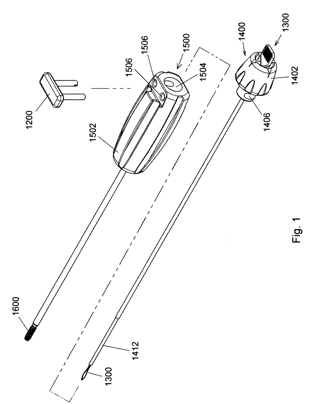
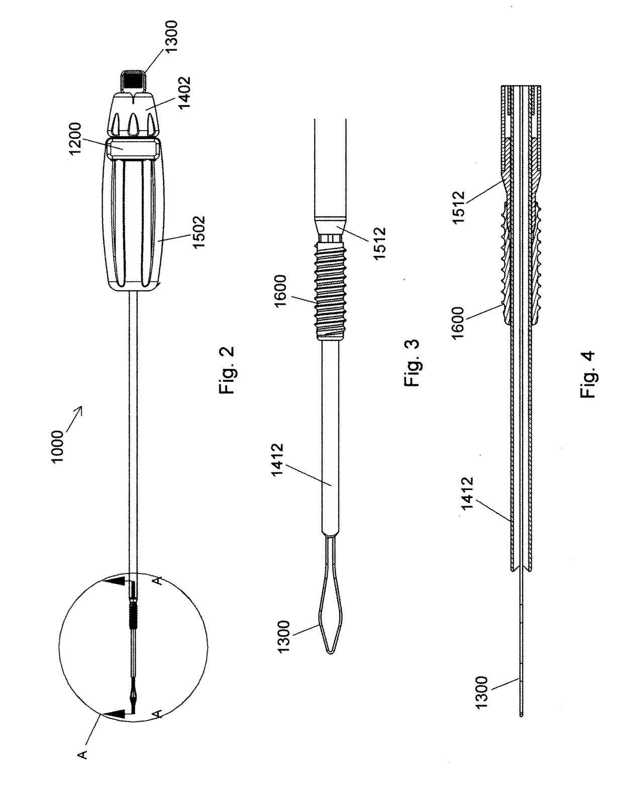
[0155]FIG. 1 depicts driver 1500 with anchor 1600 loaded thereto, tensioning (insertion) device 1400 with loading loop 1300 positioned for loading a suture, and key 1200 prior to mounting of driver 1500 to tensioning device 1400 in preparation for use. When driver 1500 is mounted to tensioning device 1400, off-axis slots 1406 of handle 1402 of tensioning device 1400 are aligned with off-axis holes 1506 of handle 1502 of driver 1500 and cylindrical portions of key 1200 are inserted into the passages so formed. Positioning of key 1200 in this manner prevents axial and rotational movement of tensioning device 1400 relative to driver 1500. FIGS. 2 through 8 depict knotless suture anchor system 1000 of the instant invention prepared for use with key 1200 and loading loop 1300 in place. Distal tubular element 1412 of tensioning device 1400 extends distally beyond anchor 1600 and distal driving element 1512 of driver 1500. Detailed descriptions of the construction and use of placement syst...


PUM


Abstract

Using the simplified placement system and method for a tissue graft anchor of the present invention, a surgeon may introduce one or more sutures into a hole in a boney tissue, apply a precise amount of tension to the sutures to advance a soft tissue graft to a desired location, and then advance the anchor into the bone, preferably while maintaining the requisite pre-determined suture tension and without introducing spin to the suture. Particularly preferred embodiments of the present invention relate to multi-anchor constructs. Multi-anchor constructs of the present invention may employ threaded implants exclusively, push-in implants exclusively, or a combination of threaded and push-in implants.

Description

PRIORITY[0001]This application is a continuation of U.S. patent application Ser. No. 15 / 256,945, filed Sep. 6, 2016 (now U.S. Pat. No. 9,717,587 issued Aug. 1, 2017), which, in turn is a continuation-in-part of U.S. patent application Ser. No. 15 / 012,060 filed Feb. 1, 2016 (now U.S. Pat. No. 9,566,060 issued Feb. 14, 2017), which, in turn, is a continuation-in-part of U.S. patent application Ser. No. 14 / 972,662 filed Dec. 17, 2015, which, in turn, is a continuation of U.S. patent application Ser. No. 14 / 636,389 filed Mar. 3, 2015 (now U.S. Pat. No. 9,226,817 issued Jan. 5, 2016), which, in turn, claims the benefit of U.S. Provisional Application Ser. No. 61 / 966,744 filed Mar. 3, 2014; 61 / 998,391 filed Jun. 26, 2014; 61 / 998,766 filed Jul. 7, 2014; and 61 / 999,405 filed Jul. 26, 2014, the contents of each of which are hereby incorporated by reference in their entirety. This application also claims the benefit of U.S. Provisional Application Ser. No. 62 / 284,151 filed Sep. 21, 2015 and 6...

Claims


Application Information

Patent Timeline
Patent Type & Authority Applications(United States)
IPC IPC(8): A61F2/08A61B17/04A61B17/00A61B17/06A61B90/00
CPCA61F2/0811A61F2002/0858A61B17/0483A61B17/0485A61B2017/00477A61B2017/044A61B2017/0409A61B2017/0427A61B2017/0445A61B2017/0458A61B2017/0496A61B2017/06042A61B2090/034A61B2090/064A61F2002/0841A61F2002/0888A61B17/0401A61F2/0805
Inventor DOUGHERTY, CHRISTOPHER P.HEISLER, GARY R.VAN WYK, ROBERT A.
Owner TENJIN
Why Eureka
Try Eureka