

Intraocular lens designs for improved stability
- Summary
- Abstract
- Description
- Claims
- Application Information
AI Technical Summary
Benefits of technology
Problems solved by technology
Method used
Image

Examples
Embodiment Construction
[0028]Reference will now be made in detail to examples of the present disclosure, which are illustrated in the accompanying drawings. Wherever possible, the same reference numbers will be used throughout the drawings to refer to the same or like parts. In the discussion that follows, relative terms such as “about,”“substantially,”“approximately,” etc. are used to indicate a possible variation of ±10% in a stated value, numeric or otherwise, unless other variations are indicated.
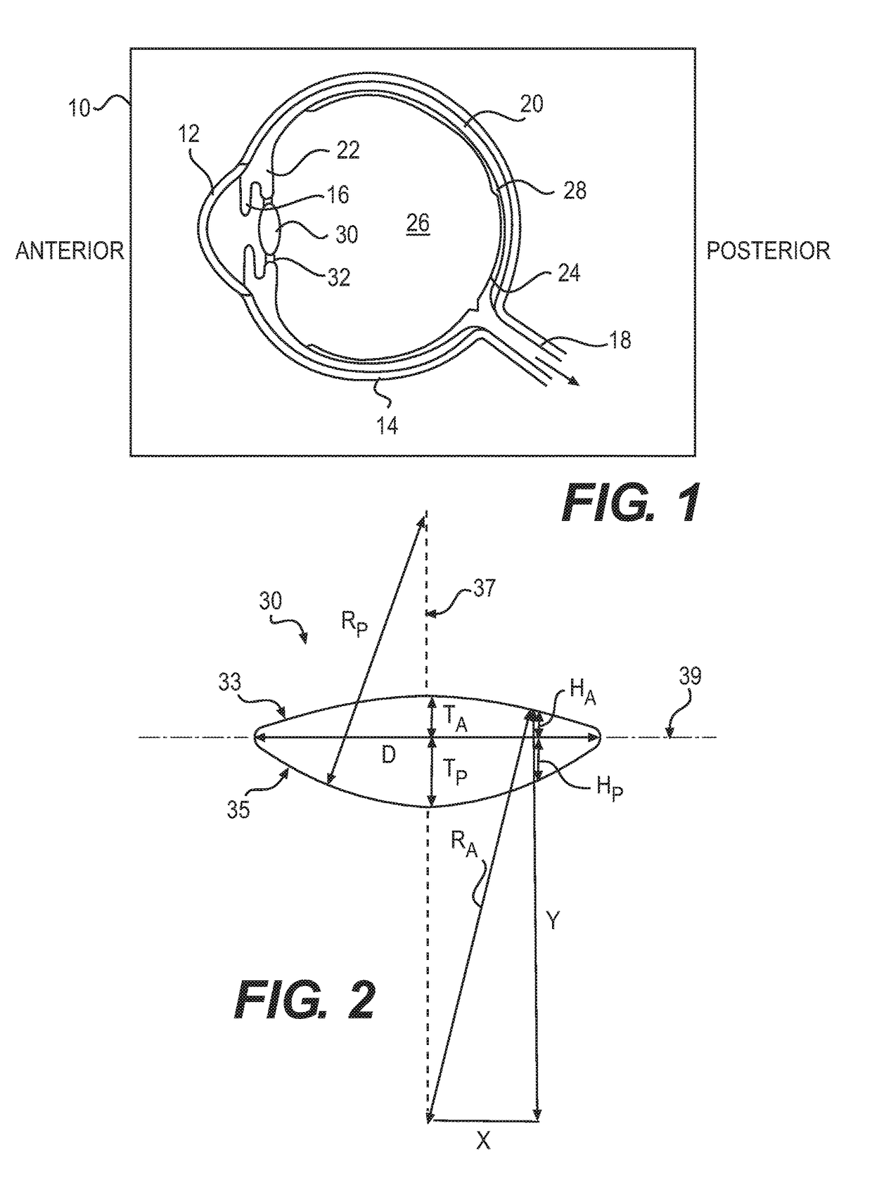
[0029]With reference to FIG. 1, the human eye 10 is shown in cross section. The eye 10 has been described as an organ that reacts to light for several purposes. As a conscious sense organ, the eye allows vision. Rod and cone cells in the retina 24 allow conscious light perception and vision including color differentiation and the perception of depth. In addition, the human eye's non-image-forming photosensitive ganglion cells in the retina 24 receive light signals which affect adjustment of the size of the pu...
PUM
 Abstract
Description
Claims
Application Information