

Golf club head
- Summary
- Abstract
- Description
- Claims
- Application Information
AI Technical Summary
Benefits of technology
Problems solved by technology
Method used
Image

Examples
first embodiment
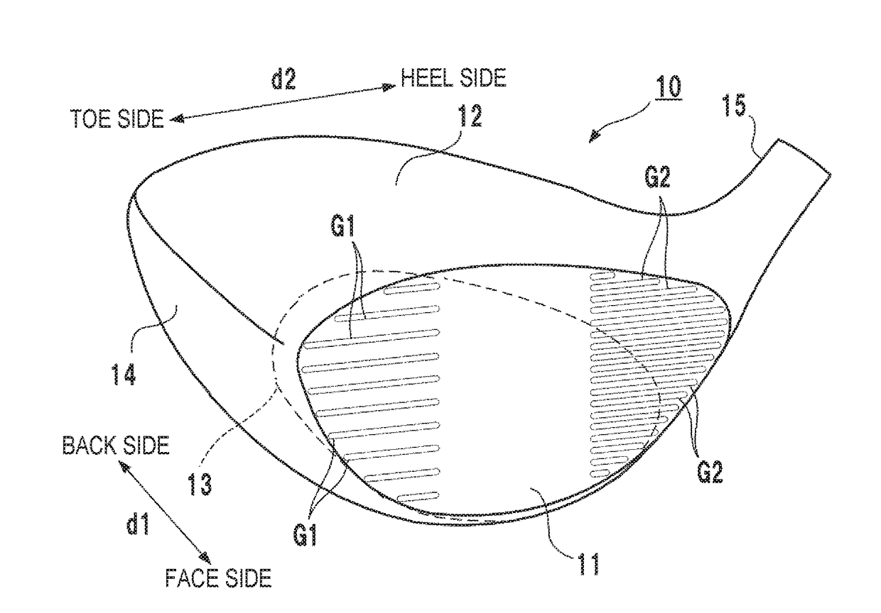
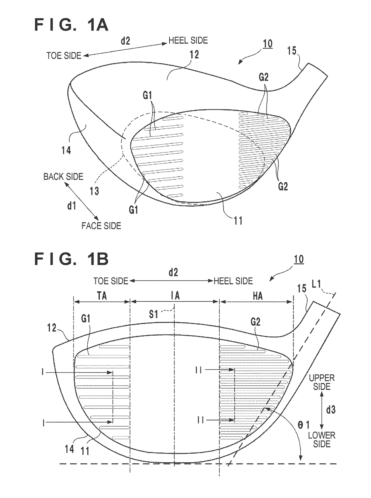
[0015]FIG. 1A is a perspective view of a golf club head 10 according to an embodiment of the present invention. FIG. 1B is a front view showing the golf club head 10 viewed from the side of a face portion 11.
[0016]The golf club head 10 forms a hollow member. Its peripheral walls form the face portion 11, a crown portion 12, a sole portion 13, and a side portion 14. The surface of the face portion 11 forms a face (striking surface). The crown portion 12 forms the upper portion of the golf club head 10. The sole portion 13 forms the bottom portion of the golf club head 10. The side portion 14 forms the portion between the sole portion 13 and the crown portion 12. The golf club head 10 also includes a hosel portion 15 to which a shaft is attached.
[0017]An arrow d1 in FIG. 1A indicates a face-back direction, and an arrow d2 indicates a toe-heel direction. An arrow d3 in FIG. 1B indicates the vertical direction of the face portion 11. The face-back direction is normally a target line dir...
second embodiment
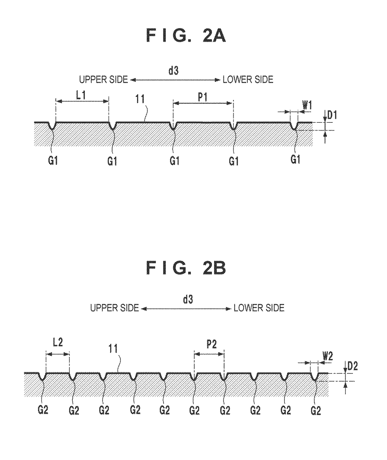
[0039]In the golf club head 10 according to the first embodiment, the number of grooves G2 in the heel-side area HA is higher in number than the number of grooves G1 of the toe-side area TA and is twice. Thus, when a golfer is at address, the heel-side area HA may seem more complicated than the toe-side area TA in the face portion 11. This may give the golfer a sense of discomfort. In order to reduce this discomfort, grooves G1 and G2 located at the same height as each other in a d3 direction may be colored by a predetermined color, while other grooves may not be colored. FIG. 4A shows such an example.
[0040]In the example of FIG. 4A, all of the grooves G1 are colored. For the grooves G2, only the grooves located at the same height as the grooves G1 are colored, and the remaining grooves are not colored. In the arrangement example of this embodiment, for the grooves G2, every other groove is colored. Since the presence of the colored grooves G1 and G2 is emphasized, the numbers of gr...
third embodiment
[0041]In the golf club head 10 according to the first embodiment, the grooves G1 and G2 are straight grooves. However, they may nave another shape. Additionally, although the grooves G1 and G2 are arranged in the d3 direction, they may be arranged in another direction. The grooves G1 and G2 may also have different shapes or arrangement directions from each other. Grooves having different shapes or arrangement directions may also be formed in the same area.
[0042]FIG. 4B shows smother arrangement example of grooves G1 and G2. In the example of FIG. 4B, a plurality of grooves G1 are formed as concentric arcs and their arrangement direction is in a d2 direction. In addition, a plurality of grooves G2 are formed as concentric arcs and their arrangement direction is in the d2 direction. In the example of FIG. 4B, the grooves G1 and G2 are concentric arcs having a common center. The grooves G1 are concentric arcs projecting toward the toe side, and the grooves G2 are concentric arcs projec...
PUM
 Abstract
Description
Claims
Application Information