Electronic device and mode switching method

An electronic device and mode switching technology, applied in mechanical mode conversion, electrical digital data processing, instruments, etc., can solve the problems of increasing the size of electronic devices, inconvenience and inconvenience to carry or hold electronic devices, etc.

Pending Publication Date: 2017-01-11
LENOVO (BEIJING) CO LTD
View PDF6 Cites 10 Cited by
  • Summary
  • Abstract
  • Description
  • Claims
  • Application Information

AI Technical Summary

Problems solved by technology

At the same time, the user's demand for display, entertainment and interactive functions of electronic equipment also promotes the trend of increasing the size of the display screen of electronic equipment, resulting in an increase in the size of electronic equipment, which brings a burden to users when carrying or holding electronic equipment. to a certain degree of inconvenience

Method used


Image

  • Electronic device and mode switching method
  • Electronic device and mode switching method
  • Electronic device and mode switching method

Examples


no. 1 approach

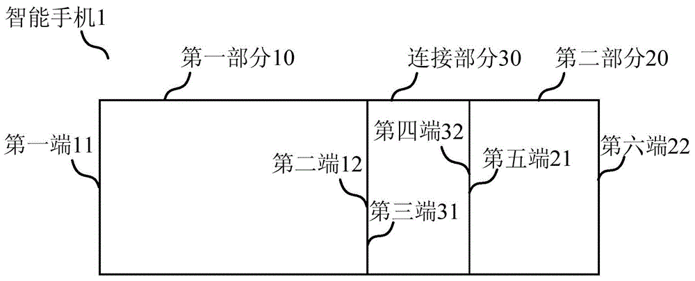
[0063] figure 1 is a top view schematically showing an electronic device according to an embodiment of the present invention. figure 2 is a side view schematically showing an electronic device according to an embodiment of the present invention. An electronic device according to an embodiment of the present invention may be an electronic device such as a tablet computer, a smart phone, a personal digital assistant, a smart wearable device, and the like. Hereinafter, for convenience of description, a smart phone will be used as an example of electronic equipment for description.

[0064] Such as figure 1 and figure 2 As shown in , the smartphone 1 includes a first part 10 , a second part 20 and a connection part 30 .

[0065] The first part 10 has a first end 11 and a second end 12, and opposite first and second surfaces 100 and 12 (not shown).

[0066] The connection part 30 has a third end 31 and a fourth end 32 , and opposite first and second surfaces 300 and 32 , whe...

no. 2 approach

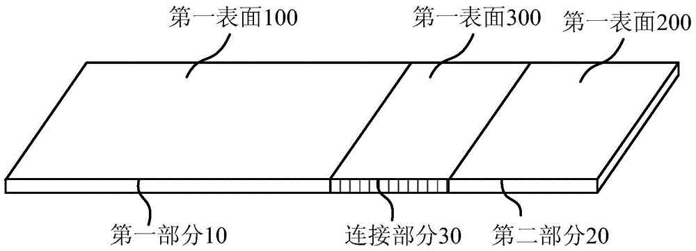
[0160] Figure 14 is a schematic diagram for explaining the basic structure of an electronic device according to the present invention. Such as Figure 14 As shown, the electronic device 1 according to the embodiment of the present invention includes a first part 10 , a second part 20 and a connection part 30 . In other words, other parts of the electronic device 1 except the first part 10 and the second part 20 are the connection part 30 .

[0161] The first part 10 has a first end 11 and a second end 12 ; the connection part 30 has a third end 31 and a fourth end 32 ; the second part 20 has a fifth end 21 and a sixth end 22 . Wherein, the first end 11 to the sixth end 22 may be the end faces of each part, or at least a part of the end faces. In the present invention, the third end 31 is connected to the second end 12, so that the first part 10 can be connected with the connecting part 30; the fifth end 21 is connected to the fourth end 32, so that the connecting part 30 ...

no. 3 approach

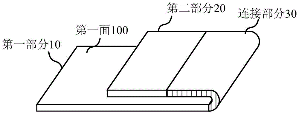
[0182] First, refer to Figure 27 An electronic device according to an embodiment of the present invention is described.

[0183] Such as Figure 27 As shown, the electronic device according to the embodiment of the present invention includes: a first part 10, which has opposite first and second faces; a connecting part 30, which has opposite first and second faces; second part 20, through which The connection part is connected to the first part and has opposite first and second faces; wherein the electronic device includes a first outer surface and a second outer surface, and the first outer surface includes a first outer surface of the first part. One surface, the first surface of the connection part and the first surface of the second part, the second outer surface includes the second surface of the first part, the second surface of the connection part and the first surface The second side of the second part.

[0184] In addition, if Figure 27 As shown, the electronic ...


PUM


Abstract

The invention discloses an electronic device. The electronic device comprises a first part, a connecting part, a second part and a display unit. The first part has a first end, a second end, and a first surface and a second surface which are opposite. The connecting part has a third end, a fourth end, and a first surface and a second surface which are opposite, wherein the third end is connected with the second end. The second part has a fifth end, a sixth end, and a first surface and a second surface which are opposite, wherein the fifth end is connected with the fourth end; the first surface of the first part, the first surface of the connecting part and the first surface of the second part form a first outer surface of the electronic device, and can relatively rotate based on the connecting part, the first part and the second part. The display unit is at least arranged on the first surface of the first part. The electronic device at least has a first pose; and under the first pose, the first surface of the first part and the first surface of the second part are in a parallel or approximately parallel state, and a first region of the display unit can be perceived.

Description

technical field [0001] The present invention relates to the field of electronic equipment, and more specifically, the present invention relates to an electronic equipment and a mode switching method. Background technique [0002] With the increasing popularity of electronic devices such as smart phones and tablet computers, users often need to carry or hold these electronic devices for a long time. At the same time, the user's demand for display, entertainment and interactive functions of electronic equipment also promotes the trend of increasing the size of the display screen of electronic equipment, resulting in an increase in the size of electronic equipment, which brings a burden to users when carrying or holding electronic equipment. To a certain degree of inconvenience. [0003] It is desired to provide an electronic device and a display method thereof, which can reduce the size of the electronic device by changing its posture, provide different display areas under di...

Claims


Application Information

Patent Timeline
Patent Type & Authority Applications(China)
IPC IPC(8): G06F1/16G06F3/01
Inventor 权镇哲李相昊
Owner LENOVO (BEIJING) CO LTD
Why Eureka
Try Eureka