System and method for detecting objects in an automotive environment

a technology for detecting objects and environments, applied in the field of computer vision algorithms, can solve the problems of increasing the complexity of the processing unit and the difficulty of running such multiple computer vision algorithms on such constrained devices

Active Publication Date: 2017-11-23
LIGHTMETRICS TECH PVT LTD
View PDF7 Cites 30 Cited by
  • Summary
  • Abstract
  • Description
  • Claims
  • Application Information

AI Technical Summary

Benefits of technology

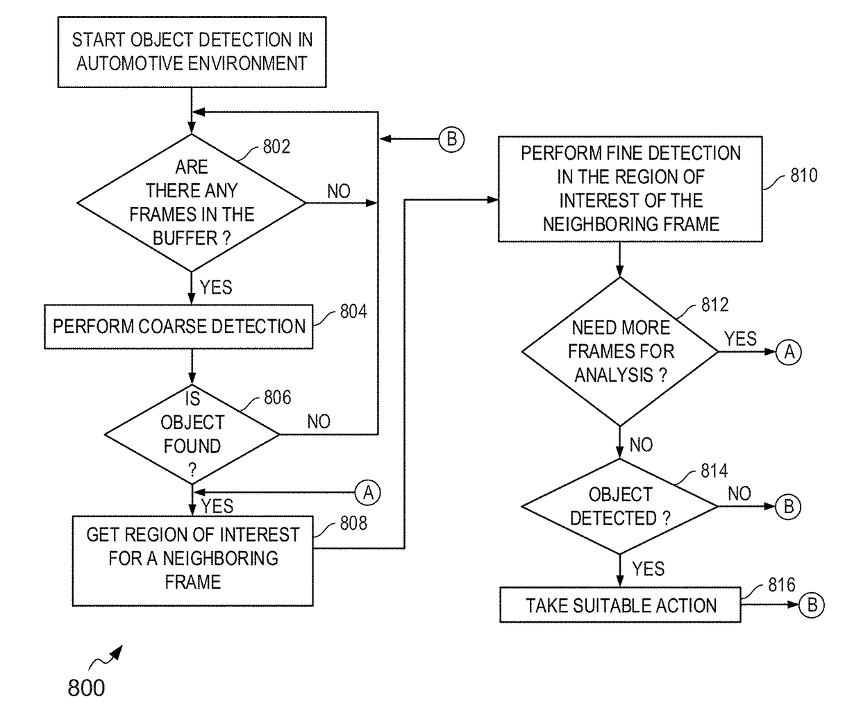
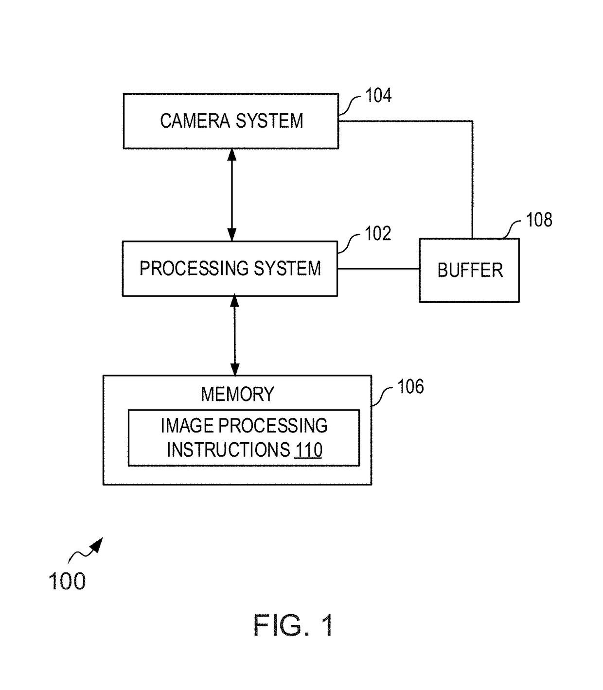
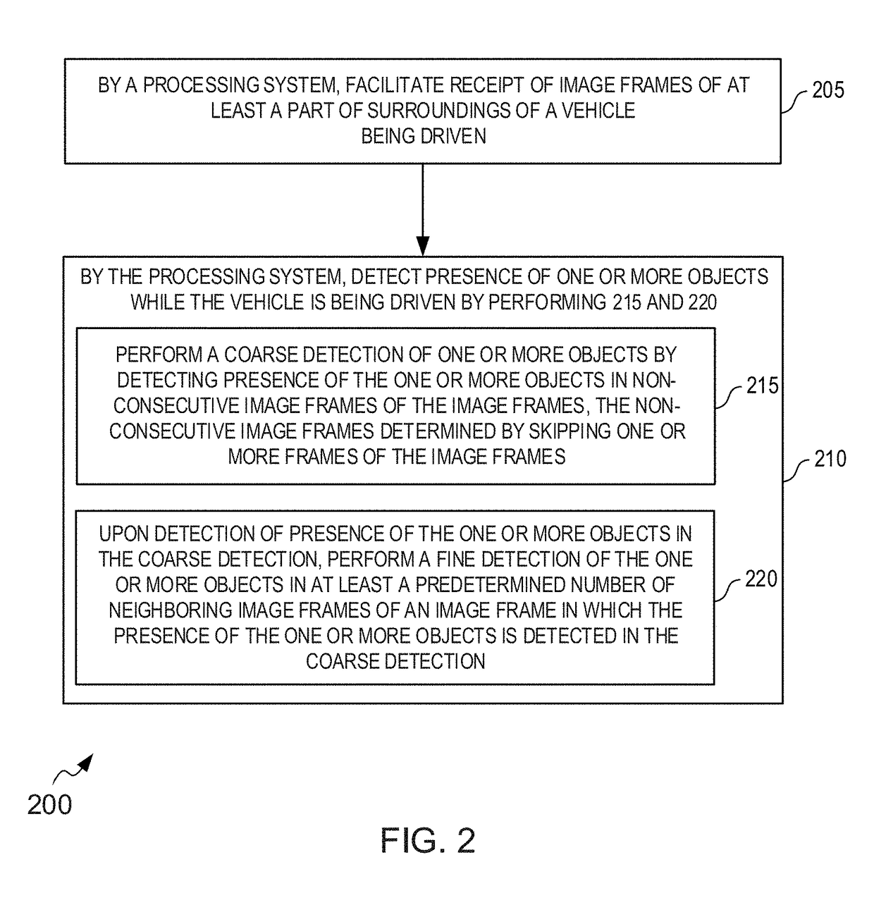
[0004]Various methods and systems are provided for object detection in an automotive environment. In an embodiment, an advanced driver assistance system (ADAS) includes a camera system, a memory and a processing system. The camera system captures image frames of at least a part of surroundings of a vehicle. The memory includes image processing instructions. The processing system is communicably coupled to the camera system for receiving the image frames. The processing system is configured to alongwith the image processing instructions stored in the memory to cause the ADAS to perform a coarse detection and a fine detection for detecting one or more objects. The coarse detection of the one or more objects is performed by detecting presence of the one or more objects in non-consecutive image frames of the image frames, where the non-consecutive image frames are determined by skipping one or more image frames of the image frames. Upon detection of the presence of the one or more objects in the coarse detection, the fine detection of the one or more objects is performed in at least a predetermined number of neighboring image frames of an image frame in which the presence of the one or more objects is detected in the coarse detection.

Problems solved by technology

However, the complexity of the processing unit increases, when the multiple computer vision algorithms are executed concurrently for detecting one or more objects, or one or more events.
Therefore, running such multiple computer vision algorithms on such constrained devices is a challenging task.

Method used


Image

  • System and method for detecting objects in an automotive environment
  • System and method for detecting objects in an automotive environment
  • System and method for detecting objects in an automotive environment

Examples


Embodiment Construction

[0019]The best and other modes for carrying out the present invention are presented in terms of the embodiments, herein depicted in FIGS. 1 to 9. The embodiments are described herein for illustrative purposes and are subject to many variations. It is understood that various omissions and substitutions of equivalents are contemplated as circumstances may suggest or render expedient, but are intended to cover the application or implementation without departing from the spirit or scope of the present invention. Further, it is to be understood that the phraseology and terminology employed herein are for the purpose of the description and should not be regarded as limiting. Any heading utilized within this description is for convenience only and has no legal or limiting effect. The terms “a” and“an” herein do not denote a limitation of quantity, but rather denote the presence of at least one of the referenced item.

[0020]Embodiments of the present disclosure provide systems and methods fo...


PUM


Abstract

Advanced driver assistance systems (ADAS) and methods for object detection such as traffic lights, speed signs, in an automotive environment, are disclosed. In an embodiment, ADAS includes camera system for capturing image frames of at least a part of surroundings of vehicle, memory comprising image processing instructions and processing system for detecting one or more objects in a coarse detection followed by a fine detection. Coarse detection includes detecting presence of the one or more objects in non-consecutive image frames of the image frames, where non-consecutive image frames are determined by skipping one or more frames of the image frames. Upon detection of presence of the one or more objects in coarse detection, fine detection of the one or more objects is performed in a predetermined number of neighboring image frames of a frame in which the presence of the objects is detected in coarse detection.

Description

FIELD OF THE INVENTION[0001]The present invention generally relates to computer vision algorithms and, more particularly to systems and methods for detecting objects in automotive environments using computer vision algorithms.BACKGROUND TO THE INVENTION[0002]Advanced Driver Assistance Systems (ADAS) installed in vehicles are useful for detecting objects such as other vehicles, pedestrians, traffic lights and signs in front of the vehicles, and generate alerts for the driver. Such systems are also useful in detecting various traffic situations including traffic jam, construction work, etc on the road and alert the driver regarding the same. A typical ADAS includes a camera placed on the dashboard of a vehicle for capturing images / videos of various events / objects in front of the vehicle, and a processing unit connected to the camera for executing multiple computer vision algorithms such as vehicle detection, pedestrian detection, traffic sign detection etc.[0003]However, the complexit...

Claims


Application Information

Patent Timeline
Patent Type & Authority Applications(United States)
IPC IPC(8): G06K9/00G08G1/052G08G1/04G06K9/78G06K9/68G06K9/20G08G1/0967G08G1/01B60R1/00
CPCG06K9/00805G06K9/78G06K9/2054G06K9/00818G06K9/00711G06K9/00825B60R2300/302G08G1/052G08G1/096783G08G1/0129G08G1/04B60R1/00G06K9/6857G01C11/04G06T2207/30261G06T7/254G06V20/582G06V20/58G06V20/584G06V30/19173B60W40/04B60W40/08G06V20/40G06V30/2504G06F18/2415
Inventor ULIYAR, MITHUNPUTRAYA, GURURAJUKIL, SOUMIKA G, KRISHNASHENOY, RAVIPATWARDHAN, PUSHKAR
Owner LIGHTMETRICS TECH PVT LTD
Why Eureka
Try Eureka