
Driving mechanism for a control valve and a control valve

a technology of driving mechanism and control valve, which is applied in the direction of valve housing, valve operating means/releasing devices, mechanical equipment, etc., can solve the problems of reducing the automatic closing time, not allowing the user to control, and not being able to control by the user

Inactive Publication Date: 2017-11-30
DURATEX
View PDF11 Cites 3 Cited by
  • Summary
  • Abstract
  • Description
  • Claims
  • Application Information

AI Technical Summary

Benefits of technology

The present invention provides a driving mechanism that is simple and robust, easy to manufacture, and has a reduced number of components. It is designed for use in control valves, such as mixing spouts or faucets, to provide both manual and automatic control for opening and closing the valve. This mechanism can be easily dismounted from the control valve for user choice of operation type, either manual closing or automatic and timed closing, by simply choosing the rotation sense for the rod-wheel assembly.

Problems solved by technology

Although both solutions, in which the driving mechanism is closed manually or in an automatic and timed manner, present advantages depending on the most adequate use condition for each operation, they have the drawback of not allowing, in a single construction, obtaining the two operational conditions to be selectively effected by the user, at his choice and according to each operation desired for the control valve and / or hydraulic device.
The above prior art solution, although allowing, with a single construction, achieving the two closing operational conditions, has the drawback of not allowing the user to control, by means of a conventional manual actuation on the driving rod which usually ends in an activation button, the time of the automatic closing of the control valve.
It is not possible for the user to control, in an easy and ergonomic way, the different closing times of the control valve for each operation of the associated hydraulic device.
Another limitation of the prior art solution discussed above is the fact of not allowing the user, upon assembly of the control valve, or even after it is assembled, in order to carry out, by means of an extremely simple operation, the reduction of the automatic closing time to a value he judges more adequate, based on the maximum closing time of the project.

Method used


Image

  • Driving mechanism for a control valve and a control valve
  • Driving mechanism for a control valve and a control valve
  • Driving mechanism for a control valve and a control valve

Examples


Embodiment Construction

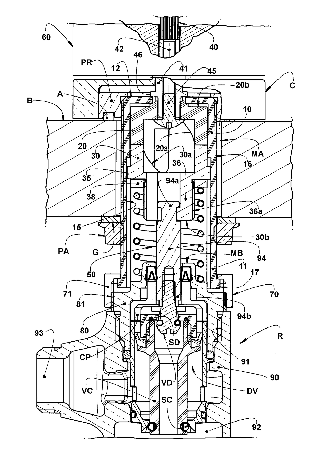
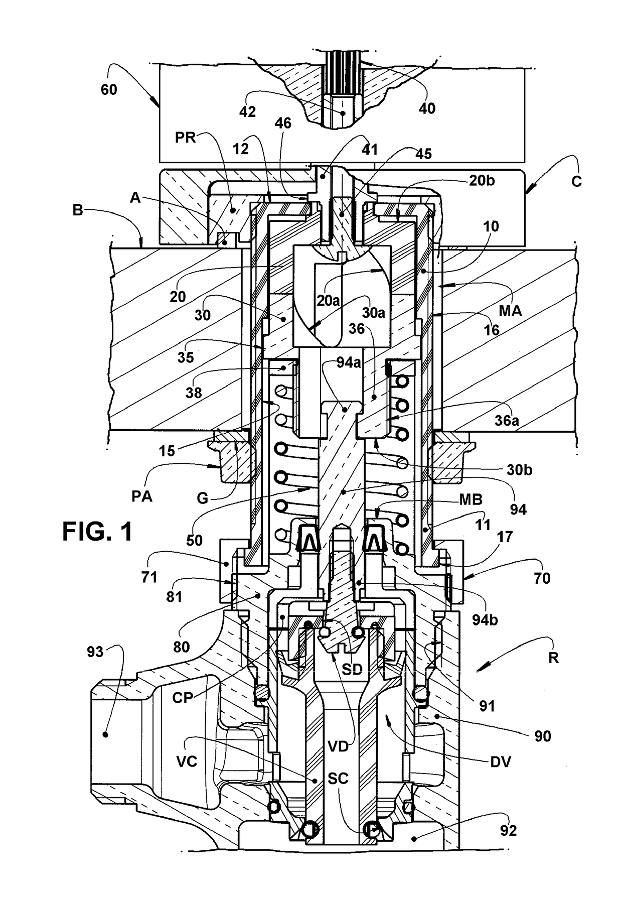
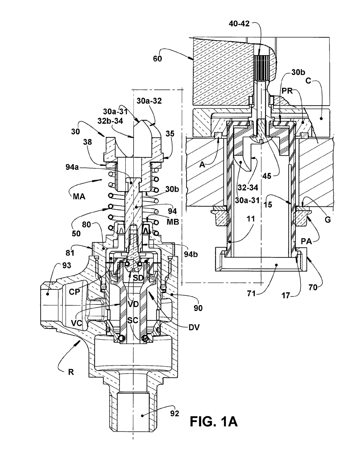
[0026]As illustrated in the appended drawings, the present driving mechanism MA is applicable to a control valve R of the type provided with a sealing device DV, which control valve R may present different constructive characteristics such as, for example, those illustrated in FIGS. 1 to 3 of the appended drawings and which will be described in further details hereinafter.

[0027]The driving mechanism MA comprises, basically: a tubular housing 10, usually cylindrical, preferably constructed in a polymeric material and presenting a mounting end 11, to be coupled to the control valve R, and a free end 12; an activating cylinder 20 and an activated cylinder 30, which are usually formed in polymeric material, provided in the interior of the tubular housing 10 and having impelling end faces 20a, 30a, maintained seated and cooperating with each other, and opposite end faces 20b, 30b, to be coupled to the driving rod 40 and to the sealing device DV, respectively.

[0028]In the illustrated cons...


PUM


Abstract

The driving mechanism has a tubular housing coupled to a control valve and housing an activating cylinder and an activated cylinder, cooperating with each other and respectively coupled to a rod of a wheel and a sealing device. The driving mechanism presents: an inoperative condition, in which the activated cylinder is maintained in a closing position of the control valve; a first operative condition, obtained by the rotation of the activating cylinder in a first sense and in which the activated cylinder is maintained in a first opening position, until the activating cylinder is rotated in an opposite sense, returning the activated cylinder to its closing position; and a second operative condition, obtained by rotation of the activating cylinder in a second sense and in which the activated cylinder reaches a second opening position, from which it is automatically displaced back to its closing position, in a timed manner.

Description

FIELD OF THE INVENTION[0001]The present invention refers to a driving mechanism to be applied in control valves in general and, more particularly, in control valves of mixing spouts or of faucets, in order to provide the manual or automatic closing of the control valve. The invention further refers to a control valve provided with said driving mechanism and incorporated to a faucet or operatively and hydraulically associated with a mixing spout or with other hydraulic device.BACKGROUND OF THE INVENTION[0002]As known in the state of the art, the control valves designed to control the supply of water to different hydraulic devices, such as spouts, faucets and the like, usually have a tubular body provided with the conventional liquid inlet and outlet openings, with an auxiliary opening, and also with an inner sealing seat which is operatively associated with a sealing means to be displaced, by a driving mechanism, between closing and opening positions of the control valve.[0003]There ...

Claims


Application Information

Patent Timeline
Patent Type & Authority Applications(United States)
IPC IPC(8): F16K31/524F16K27/02F16K11/22F16K1/42E03C1/04F16K31/56
CPCF16K31/52433F16K1/427E03C1/04F16K11/22F16K31/563F16K27/0236F16K1/34F16K27/02F16K31/52408
Inventor GONZALEZ, DANIEL
Owner DURATEX
Learn More