
Vessel steering apparatus

a steering device and vessel technology, applied in the direction of steering initiation, vessel construction, instruments, etc., can solve the problems of frequent on and off operations of the driving device, complicated steering operation of the ship, etc., and achieve the effects of convenient steering operation, easy control, and complicated steering operation

Active Publication Date: 2017-12-07
YANMAR POWER TECHNOLOGY CO LTD
View PDF3 Cites 31 Cited by
  • Summary
  • Abstract
  • Description
  • Claims
  • Application Information

AI Technical Summary

Benefits of technology

The present invention provides a ship steering device that can move the ship in a straight line even when it makes a turn while keeping it at target coordinates in a target bearing. This is achieved by setting a control mode for each behavior of the ship in each zone to shift to and considering the influence of the way the ship is used and disturbances like water current or wind. The device helps to simplify the steering operation of the ship while keeping it at the target coordinates.

Problems solved by technology

When positioning the hull of a ship having the above configuration, it is necessary to steer the ship in consideration of mutual influence between the side thruster and the forward-backward propeller, and thus a steering operation of the ship is complicated.
When the ship according to Patent Document 1 is to be positioned at a target position designated by using a GPS device and a heading sensor, the hull of the ship cannot be settled at the target position due to water current, wind, and the like, or an inertial force (way of the ship), thereby causing in frequent on and off operations of a driving device.

Method used


Image

  • Vessel steering apparatus
  • Vessel steering apparatus
  • Vessel steering apparatus

Examples


Embodiment Construction

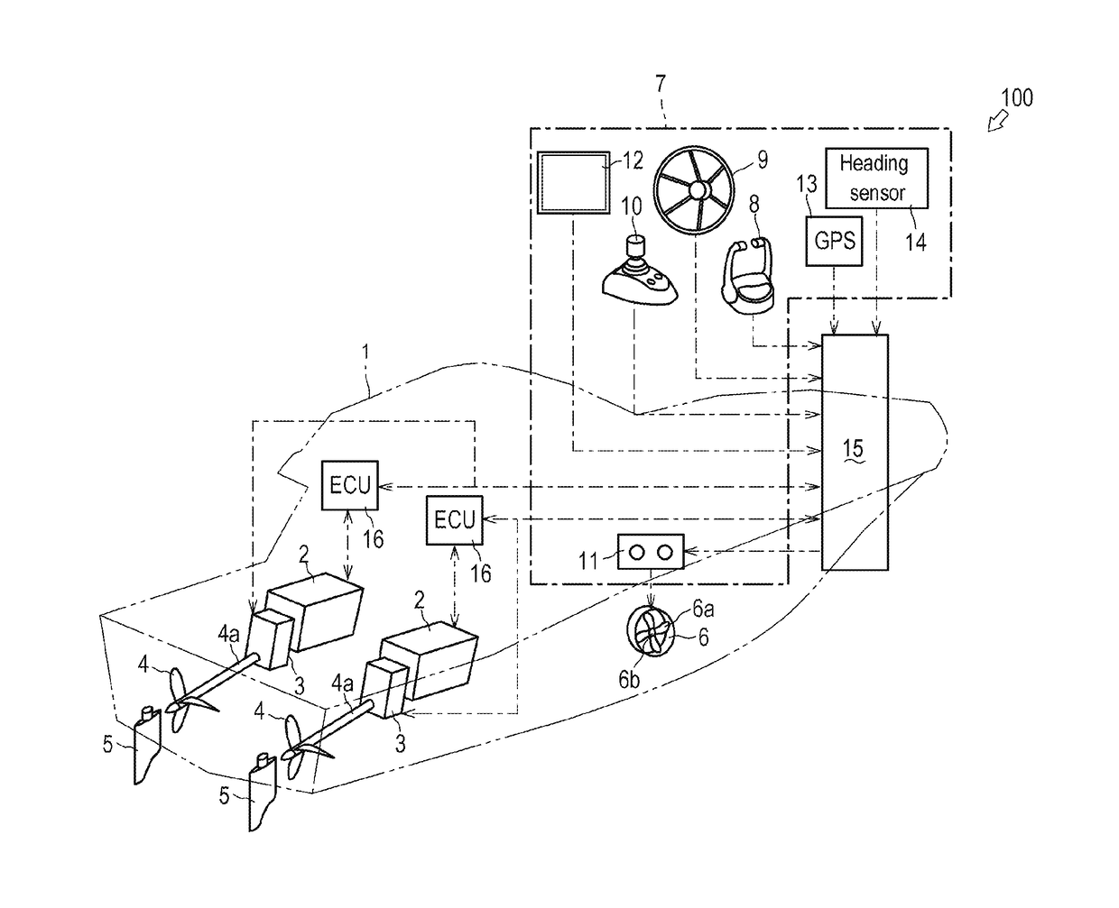
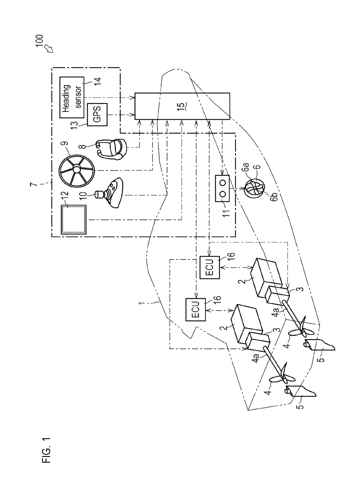
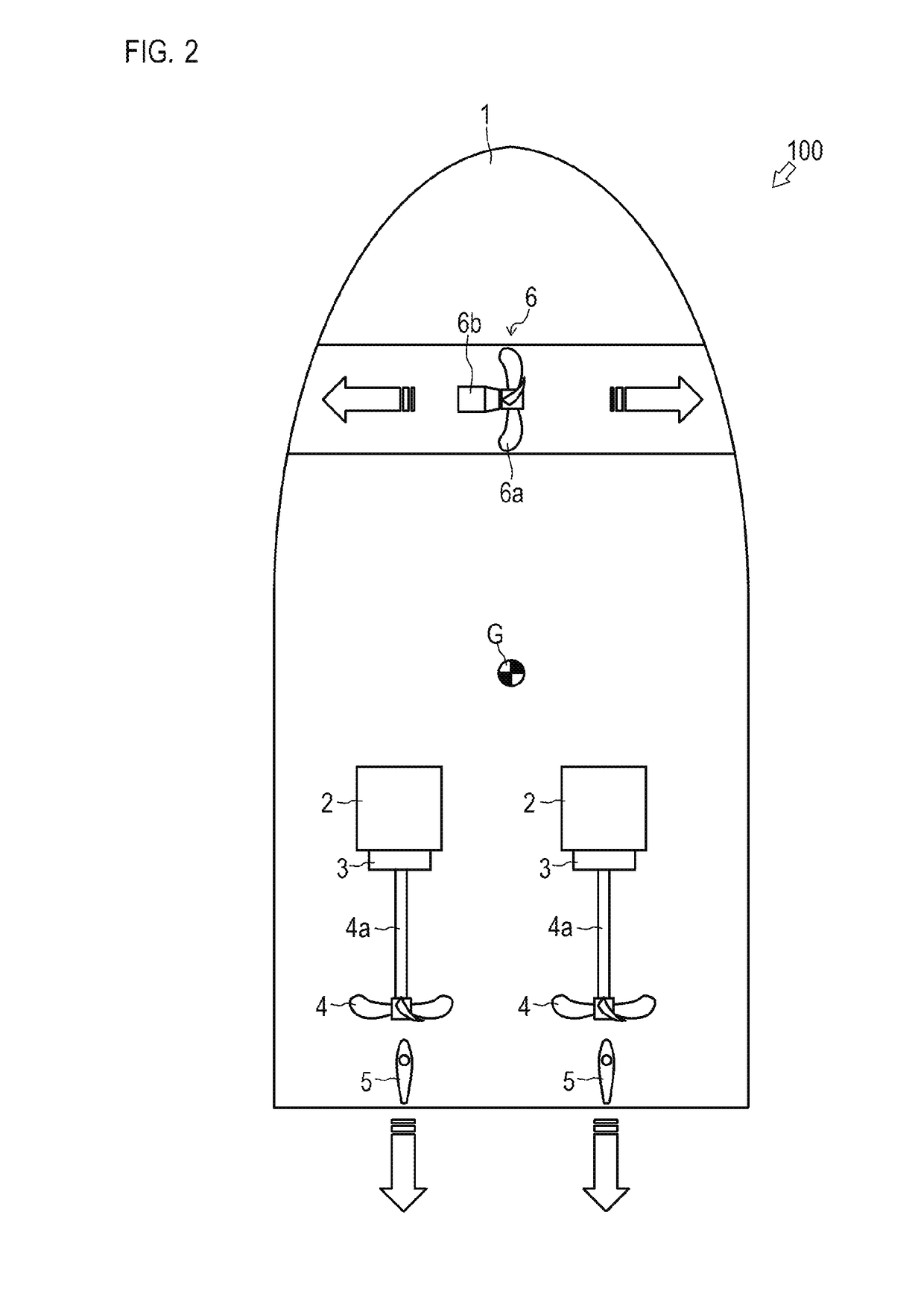
[0041]An overall outline and configuration of a ship 100, which is one embodiment of the present invention, are described with reference to FIGS. 1 to 3. Note that the ship 100 in FIG. 1 is a ship with the so-called two-axis propulsion system (inboard boat). However, the number of the propulsion axes and the form of the propulsive devices are not limited thereto, and the ship may have a plurality of axes or have an out-drive system. In this embodiment, the direction of the bow of the ship 100 is defined as the fore side, and the fore-and-aft direction and the left-and-right direction are defined accordingly.

[0042]Referring to FIGS. 1 and 2, the ship 100 is an inboard boat in which power from engines 2 is transmitted to forward-backward propellers 4 through propeller shafts 4a, respectively. The hull 1 of the ship 100 includes propulsion apparatuses including the engines 2, switching clutches 3, the forward-backward propellers 4, rudders 5, a side thruster 6, and ECUs 16, and also in...


PUM


Abstract

For a vessel steering apparatus for performing a movement control to move a vessel to a target position on the basis of a signal of a GPS apparatus, a movement control stop area, a buffer area adjacent to the movement control stop area, and a movement-controlling area adjacent to the buffer area are set on the basis of the distance from the target position, wherein in the movement control stop area, thrust generation by a propulsion apparatus is stopped; in the movement-controlling area, thrust is generated by the propulsion apparatus; and in the buffer area, thrust is generated by the propulsion apparatus of the vessel for movement control only in the case where the vessel moves from the movement-controlling area to the buffer area, then stays in the buffer area, and moves in a direction away from the target position.

Description

CROSS REFERENCE TO RELATED APPLICATIONS[0001]This is the U.S. national stage of application No. PCT / JP2015 / 73666, filed on Aug. 24, 2015. Priority under 35 U.S.C. §119(a) and 35 U.S.C. §365(b) is claimed from Japanese Application No. 2014-216750, filed on Oct. 23, 2014, and Japanese Application No. 2014-216751, filed on Oct. 23, 2014, the disclosures of which are also incorporated herein by reference.TECHNICAL FIELD[0002]The present invention relates to a ship steering device.BACKGROUND ART[0003]Conventionally, a ship (inboard boat) in which power is transmitted from a prime motor (engine) provided inside a hull to a forward-backward propeller provided outside the hull through a switching clutch and a propeller shaft has been known. A ship with a side thruster for a lateral movement in a rightward or leftward direction to improve the maneuverability at the time of landing or the like has also been known. The side thruster is formed of a propeller provided near the lateral center on ...

Claims


Application Information

Patent Timeline
Patent Type & Authority Applications(United States)
IPC IPC(8): B63H21/21B63H25/02B63H25/42B63J99/00
CPCB63H21/21B63H25/02B63B2721/00B63J2099/008B63H25/42B63H25/04B63B49/00G05D1/0206B63H2025/026B63H2025/045B63B79/10
Inventor HARA, NAOHIROWAKAHARA, HIROAKIWATANABE, JUNTAMURA, GAKUJI
Owner YANMAR POWER TECHNOLOGY CO LTD
Learn More