
Spring vent of tire vulcanizing mold

Active Publication Date: 2017-12-07
MEGA IND CO LTD
View PDF5 Cites 0 Cited by
  • Summary
  • Abstract
  • Description
  • Claims
  • Application Information

AI Technical Summary

Benefits of technology

The present invention aims to improve the structure of a spring vent in a tire vulcanizing mold. The goal is to make it easier to replace the rod at the sleeve in the assembled state of the spring vent and mold, which reduces maintenance costs and increases work efficiency.

Problems solved by technology

As a result, air is exhausted through the spring vents.
However, according to the mini vent including the above-described components, for replacement of the valve structure, the engagement parts protruding from the inner diameter of the casing are damaged using a tool so that the stopper of the valve structure is capable of passing through the vent hole of the casing, and then the valve structure is lifted upwards to separate the valve structure from the casing.
However, when the engagement parts are damaged using the tool, the casing and valve structure are damaged and are not restored to the original shape thereof, such that the entire mini vent should be replaced.
Thus, it is inconvenient to replace the valve structure in the casing, and, as such, maintenance costs are increased and work efficiency is decreased.

Method used


Image

  • Spring vent of tire vulcanizing mold
  • Spring vent of tire vulcanizing mold
  • Spring vent of tire vulcanizing mold

Examples


Embodiment Construction

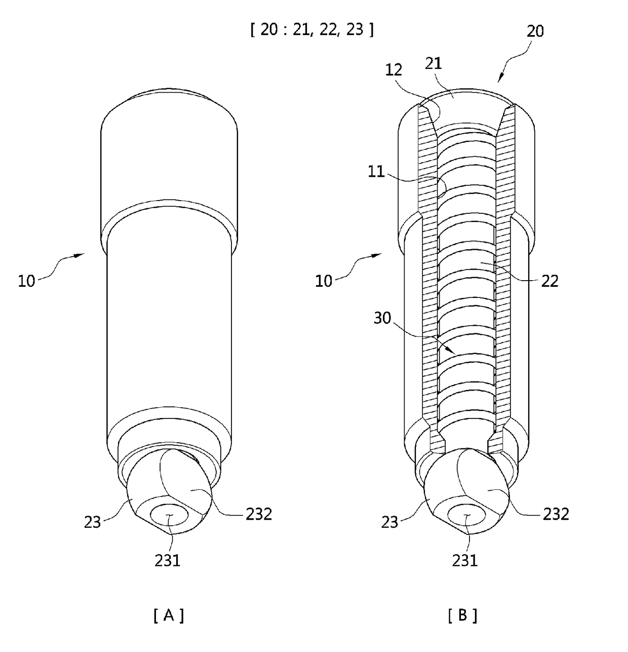
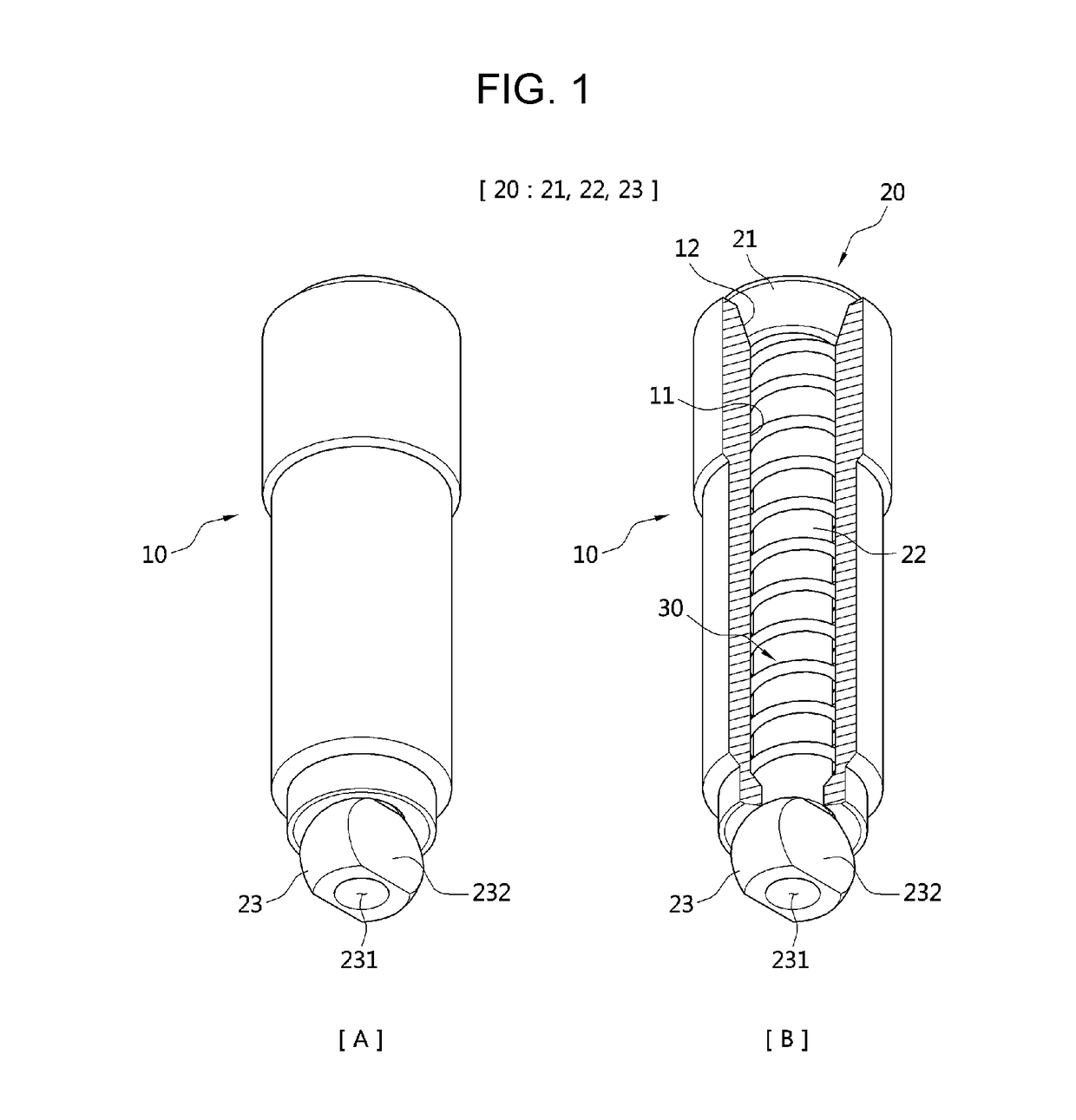
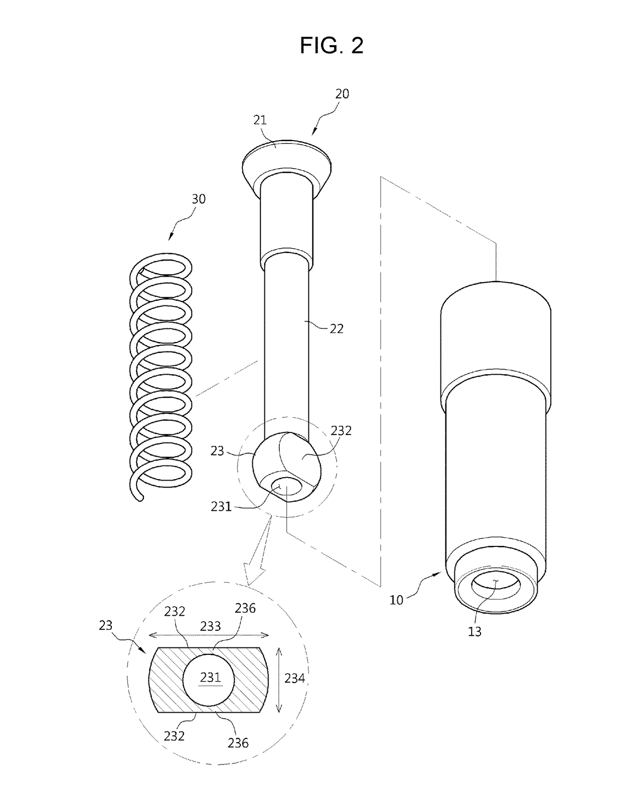
[0030]Hereinafter, exemplary embodiments of the present invention are described in detail with reference to the accompanying drawings. Particular terms may be defined to describe the invention in the best manner. Accordingly, the meaning of specific terms or words used in the specification and the claims should not be limited to the literal or commonly employed sense, but should be construed in accordance with the spirit of the invention. The description of the various embodiments is to be construed as exemplary only and does not describe every possible embodiment of the invention. Therefore, it should be understood that various changes may be made and equivalents may be substituted for elements of the invention.

[0031]In addition, a direction toward a head 1 is referred to as an upper direction and a direction toward a stopper 23 is referred to as a lower direction in accordance with FIG. 1.

[0032]According to the illustrated embodiment of the present invention, the spring vent for t...


PUM

PropertyMeasurementUnit
Shapeaaaaaaaaaa

Abstract

A spring vent for a tire vulcanizing mold comprises: a sleeve having a flow path vertically passing therethrough; a head opening / closing an inlet at an upper end of the flow path; a rod comprising a bar-type body formed below the head and disposed along the flow path and a stopper formed below the body to be hung to an outside of an outlet at a lower end of the flow path; and a spring inserted into the body. The stopper of the rod is formed to have a spherical shape. An elastic hole having an open bottom is formed in the stopper.

Description

BACKGROUND OF THE INVENTIONField of the Invention[0001]The present invention relates to a spring vent of a tire vulcanizing mold for exhausting air between a tire and the vulcanizing mold during vulcanization, more particularly to a spring vent of a tire vulcanizing mold, in which, due to structural improvement of the spring vent, a rod is easily replaced at a sleeve in an assembled state of the spring vent and mold, thereby reducing maintenance costs and increasing work efficiency.Description of the Related Art[0002]Generally, a tire vulcanizing mold process includes inserting a green tire (raw tire) into a uniform mold, and applying heat and pressure inside and outside of the mold to perform a reaction between rubber and sulfur or other chemicals, thereby forming a tire.[0003]During molding a tire, the spring vents for the tire vulcanizing mold are used to exhaust air between the green tire and the vulcanizing mold.[0004]That is, a plurality of drill holes is formed at the vulcani...

Claims


Application Information

Patent Timeline
IPC IPC(8): F16K24/04B29C33/10B29D30/06F16K17/04
CPCF16K24/04B29C33/10B29D2030/0617F16K17/04B29D30/0606B23P15/001F16K1/00F16K1/32F16K15/18F16K15/20B29C35/02B29D30/02
Inventor SEO, SEOK JUN
Owner MEGA IND CO LTD
Learn More