
Magnetic locking utility knife

a technology of magnetic locking and utility knives, applied in the field of utility knives, can solve the problems of exposing users to potential hazardous injuries, worn out locking mechanisms for maintaining exposed blades, etc., and achieve the effect of allowing for quick and safe exposure of blades

Inactive Publication Date: 2017-12-14
TRIMARCHE ROBERT +2
View PDF15 Cites 0 Cited by
  • Summary
  • Abstract
  • Description
  • Claims
  • Application Information

AI Technical Summary

Benefits of technology

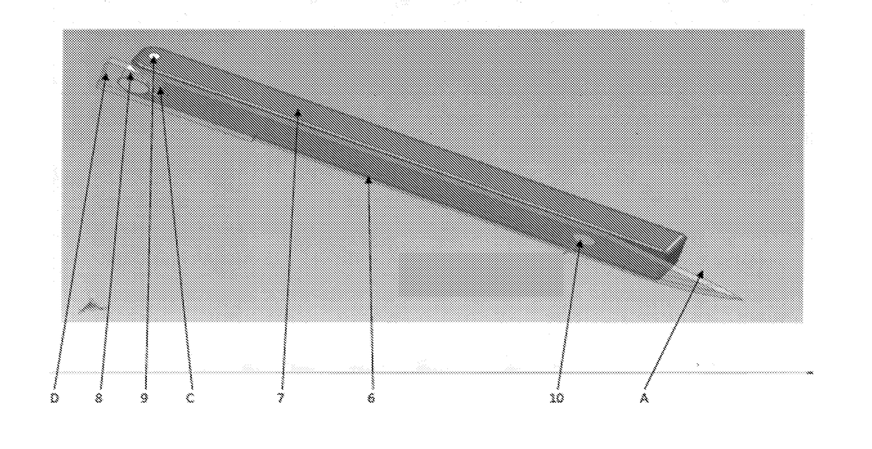
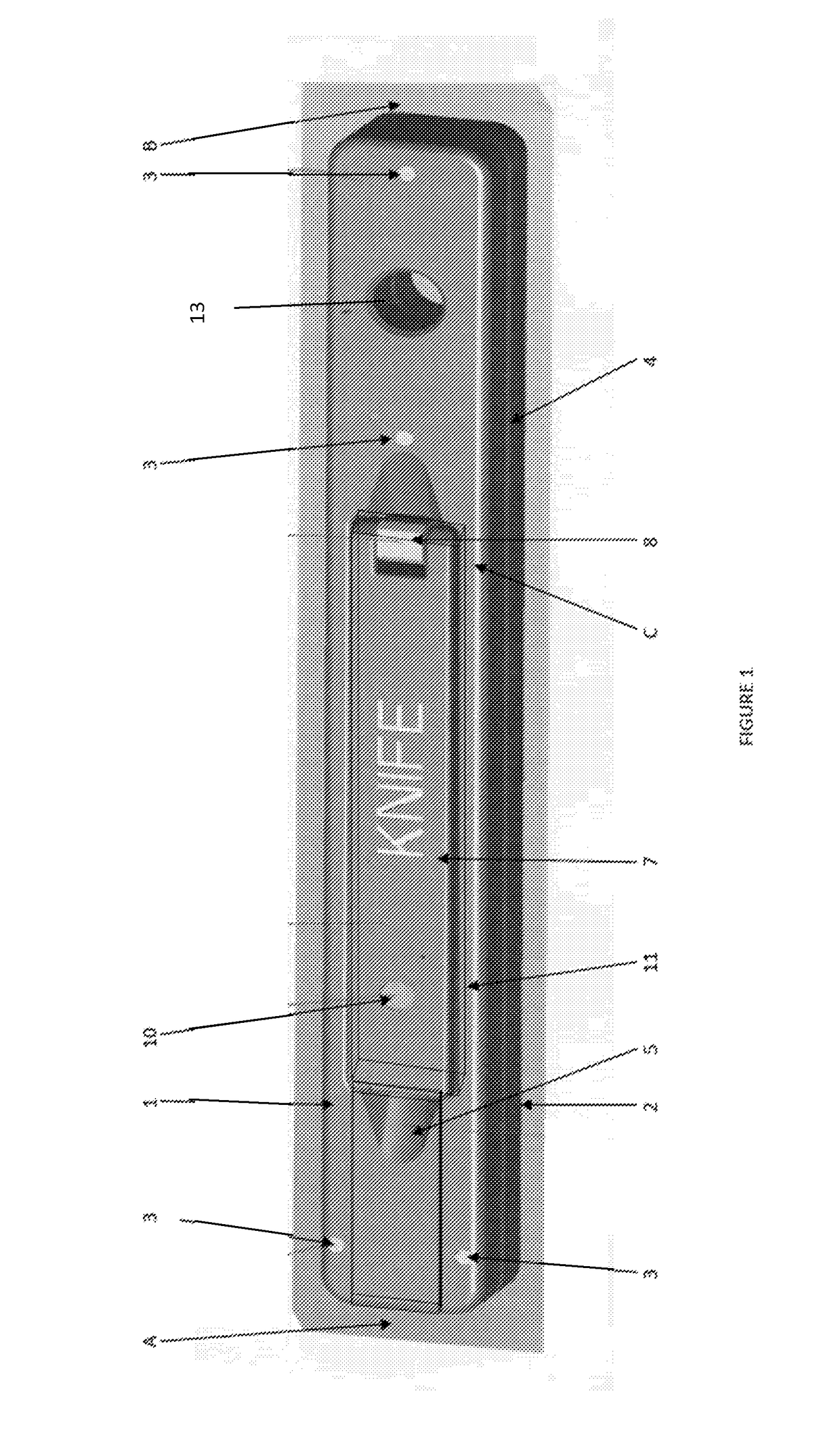
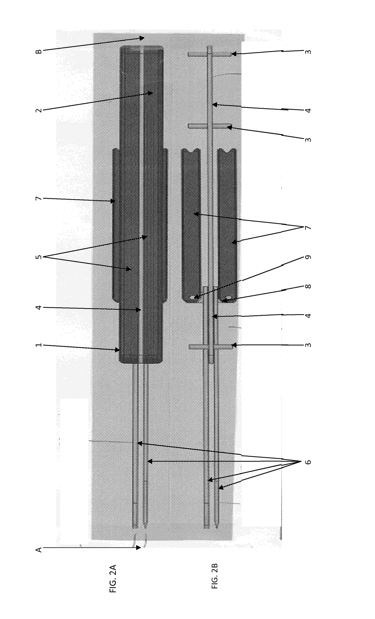
This patent is about a utility knife with a retractable blade that can be extended and retracted out of a uniquely designed handle. The handle has a lever arm that can be extended from either side and is attached to the blade to extend and retract it. Once the blade is fully exposed or retracted, the end of the handle will rotate back to the base and will magnetically be held and locked in place. This design allows the user to safely and quickly expose the blade without exposing themselves to the cutting edge of the blade. There are also modifications that can allow for multiple blades and detachable blades.

Problems solved by technology

Locking mechanisms for maintaining exposed blades can be worn out overtime, exposing the user to potential hazardous injury due to the blade not maintaining its fixed position.

Method used


Image

  • Magnetic locking utility knife
  • Magnetic locking utility knife
  • Magnetic locking utility knife

Examples


Embodiment Construction

[0026]Reference will now be made in detail to exemplary embodiments, examples of which are illustrated in the accompanying drawings, wherein like reference numerals refer to like elements throughout. However, known functions associated with the exemplary embodiments or detailed descriptions on the configuration and other matters which would unnecessarily obscure the present disclosure will be omitted.

[0027]Although exemplary embodiments of the disclosure have been shown and described, it would be appreciated by those skilled in the art that changes may be made in these exemplary embodiments without departing from the principles and spirit of the exemplary embodiments, the scope of which is defined in the claims and their equivalents. For example, while one use of the invention is in the medical field as a surgical scalpel, the same principles could be used to make devices for other medical and non-medical fields.

[0028]The embodiment of the current invention is shown generally in FIG...


PUM


Abstract

A utility tool device including a handle with a tool recess and a lever arm recess; a rotatable lever arm with a magnet that is configured to fit in the lever arm recess; and a rotatable lever hinge attached to the lever arm and configured to attach to a tool; wherein the tool recess is configured to have a tool fit in the tool recess; and wherein the magnet is configured to lock a tool in place when the lever arm is in the lever arm recess.

Description

CROSS-REFERENCE TO RELATED APPLICATION[0001]This application claims priority from U.S. Provisional Application No. 62 / 083,497 filed Nov. 24, 2014, the disclosure of which is incorporated herein by reference.BACKGROUND1. Field[0002]Exemplary embodiments relate to utility knife, in particular, to a utility knife having a safer blade extending / retracting mechanism with a unique design for a magnetic locking handle.2. Description of the Related Art and Background[0003]Utility knives are commonly used in various settings for a myriad of purposes. There are currently multiple designs for extending and retracting the blade of these utility knifes. Locking mechanisms for maintaining exposed blades can be worn out overtime, exposing the user to potential hazardous injury due to the blade not maintaining its fixed position.[0004]It is therefore an object of this invention to provide a safe utility knife with a retractable blade that prevents or at least minimizes the chance of operator injury...

Claims


Application Information

Patent Timeline
Patent Type & Authority Applications(United States)
IPC IPC(8): B26B5/00A61B17/3213B26B11/00A61B17/00A61B17/3211A61B90/00
CPCB26B5/003B26B11/00B26B5/008A61B17/3213A61B2090/034A61B2017/32113A61B2017/00876A61B2017/0088A61B2017/0023B26B1/08
Inventor TRIMARCHE, ROBERTELLEGALA, DILANTHA B.DUDLEY, CALVIN
Owner TRIMARCHE ROBERT
Learn More