Rotational joint for an aircraft folding wing and method of assembly

Active Publication Date: 2017-12-14
AIRBUS OPERATIONS LTD
View PDF6 Cites 20 Cited by
  • Summary
  • Abstract
  • Description
  • Claims
  • Application Information

AI Technical Summary

Benefits of technology

[0061]Optionally the at least one fastener is a releasable fastener such that the first and second parts may be detached from each other. This may advantageously allow for the rotational joint to be dissembled and repaired or replaced.
[0062]In embodiments of the invention, said radial retention is such that radial movement of

Problems solved by technology

It may otherwise be difficult or impossible to receive the male member in the female member, as the inner race is received in the outer race, since the male and female members are configured such that when the male m

Method used


Image

  • Rotational joint for an aircraft folding wing and method of assembly
  • Rotational joint for an aircraft folding wing and method of assembly
  • Rotational joint for an aircraft folding wing and method of assembly

Examples


Embodiment Construction

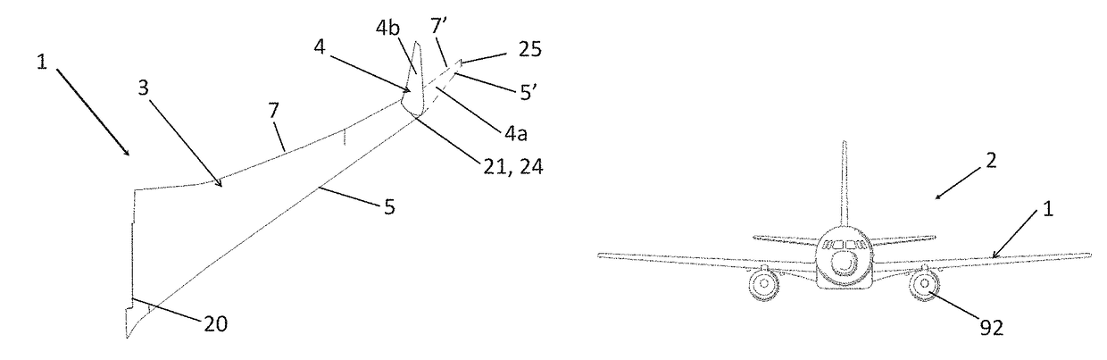
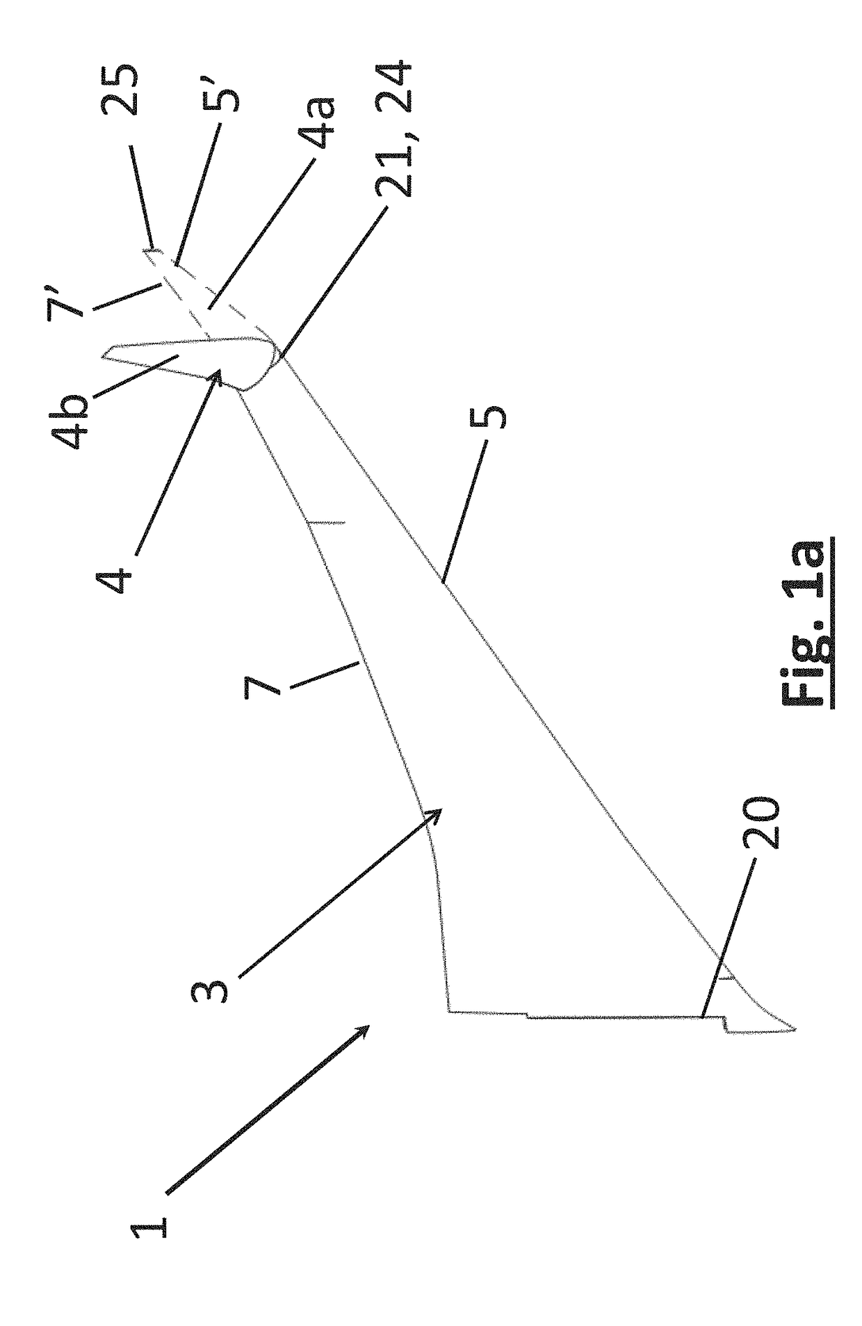
[0133]FIG. 1a is a perspective view of an aircraft wing 1 according to an embodiment of the invention, of an aircraft 2. The aircraft wing 1 comprises a fixed wing 3 and a wing tip device 4.

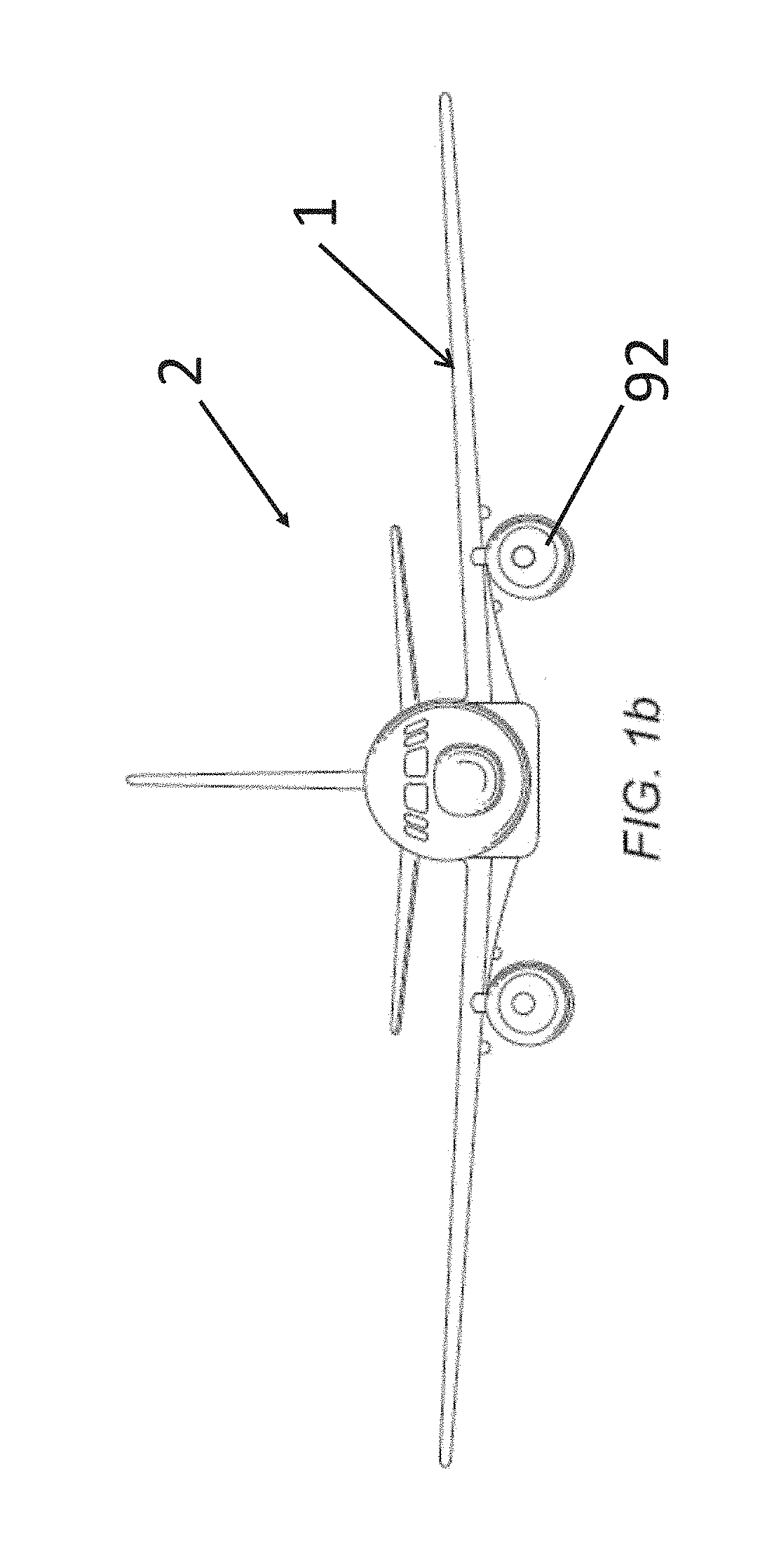
[0134]The aircraft 2 is a passenger aircraft comprising a passenger cabin comprising a plurality of rows and columns of seat units for accommodating a multiplicity of passengers, in this case more than 50 passengers. The aircraft is a powered aircraft and comprises engines 92, mounted under the wings 1, for propelling the aircraft 2.

[0135]The fixed wing 3 extends outboard from the fuselage of the aircraft, in a spanwise direction from a root 20 to a tip 21. The fixed wing 3 also extends in a chord-wise direction from a leading edge 5 to a trailing edge 7.

[0136]The wing tip device 4 is located at the outboard tip 21 of the fixed wing 3. In the described embodiment, the wing tip device 4 is in the form of a planar wing tip extension, although the invention is also applicable to other types of wing ...


PUM


Abstract

A method of rotatably couple a wing tip device (4) to a fixed wing (3) by a rotational joint (101) having an outer race (8) and an inner race (9) that is received in the outer race (8) one of the inner and outer races comprises a male member (76) and the other is a two-part assembly comprising a first part (9a) and a second part (9b) that together form a female member (72), the method brings the first and second parts together to form the female member (72) about the male member (76) such that the male member (76) is received in the female member (72) and fixing the first and second parts (9a, 9b) such that the race that is rotationally fixed relative to the wing tip device (4) is axially and radially retained relative to the race that is rotationally fixed relative to the fixed wing (3).

Description

RELATED APPLICATION[0001]This application claims priority to and incorporates by reference United Kingdom (GB) patent application 1610105.7 filed Jun. 9, 2016.BACKGROUND OF THE INVENTION[0002]The present invention relates to aircraft comprising foldable wings, rotational joints for use on such aircraft and to methods of assembly of such rotational joints and foldable aircraft wings.[0003]There is a trend towards increasingly large passenger aircraft with higher performance efficiency (for example fuel burn reduction), for which it is desirable to have correspondingly large wing spans. However, the maximum aircraft span is effectively limited by airport operating rules which govern various clearances required when maneuvering around the airport (such as the span and / or ground clearance required for gate entry and safe taxiway usage).[0004]In some suggested designs, aircraft are provided with wings that have a fixed wing and a wing tip device that is rotatably coupled to the tip of th...

Claims


Application Information

Patent Timeline
IPC IPC(8): B64C3/56B64F5/10
CPCB64F5/10B64C3/56Y02T50/10
Inventor BISHOP, BENJAMIN
Owner AIRBUS OPERATIONS LTD
Why Eureka
Try Eureka