Posterior dynamic stabilizer devices

a dynamic stabilizer and anterior stabilizer technology, applied in the field of spinal instrumentation, can solve the problems of further damage, disadvantageous caps, limited use of capping techniques, etc., and achieve the effect of controlling movemen

Inactive Publication Date: 2006-04-20
DEPUY SPINE INC (US)
View PDF98 Cites 278 Cited by
  • Summary
  • Abstract
  • Description
  • Claims
  • Application Information

AI Technical Summary

Benefits of technology

[0008] The present invention provides various methods and devices for repairing and / or replacing a damaged facet joint, and optionally for replacing other posterior elements, including, for example, the lamina, the posterior ligaments, and / or other features of a patient's spinal column. In one exemplary embodiment, an implantable device for replacing and / or stabilizing one or more facet joints in a patient's spinal column is provided and it generally includes at least one dynamic stabilizing member, e.g., a flexible member, and at least one stabilizing rod or connector that is adapted to couple to adjacent vertebrae and that is adapted to extend through the at least one flexible member. In an exemplary embodiment, the device includes superior and inferior connector members that are adapted to mate to superior and inferior vertebrae, respectively, and the flexible member(s) is adapted to span across at least two adjacent vertebrae in a patient's spinal column. In use, the superior and inferior connectors and the flexible member(s) are effective to control movement between the superior and inferior vertebrae. More preferably, the connector(s) are adapted to slidably and / or rotatably move relative to the flexible member(s), preferably without deforming the flexible member(s), when the adjacent vertebrae are moved within a first range of motion, and they are preferably adapted to deform the flexible member(s) when the adjacent vertebrae are moved within a second range of motion beyond the first range of motion.

Problems solved by technology

As a result, additional stress may be applied to the adjoining levels, thereby potentially leading to further damage.
Capping techniques, however, are limited in use as they will not remove the source of the pain in osteoarthritic joints.
Caps are also disadvantageous as they must be available in a variety of sizes and shapes to accommodate the wide variability in the anatomical morphology of the facets.
Caps also have a tendency to loosen over time, potentially resulting in additional damage to the joint and / or the bone support structure containing the cap.
One drawback of current articulating facet replacement devices, however, is that they require the facet joints to be resected.
Moreover, alignment of the articulating surfaces with one another can be challenging.

Method used


Image

  • Posterior dynamic stabilizer devices
  • Posterior dynamic stabilizer devices
  • Posterior dynamic stabilizer devices

Examples


Embodiment Construction

[0045] Certain exemplary embodiments will now be described to provide an overall understanding of the principles of the structure, function, manufacture, and use of the devices and methods disclosed herein. One or more examples of these embodiments are illustrated in the accompanying drawings. Those skilled in the art will understand that the devices and methods specifically described herein and illustrated in the accompanying drawings are non-limiting exemplary embodiments and that the scope of the present invention is defined solely by the claims. The features illustrated or described in connection with one exemplary embodiment may be combined with the features of other embodiments. Such modifications and variations are intended to be included within the scope of the present invention.

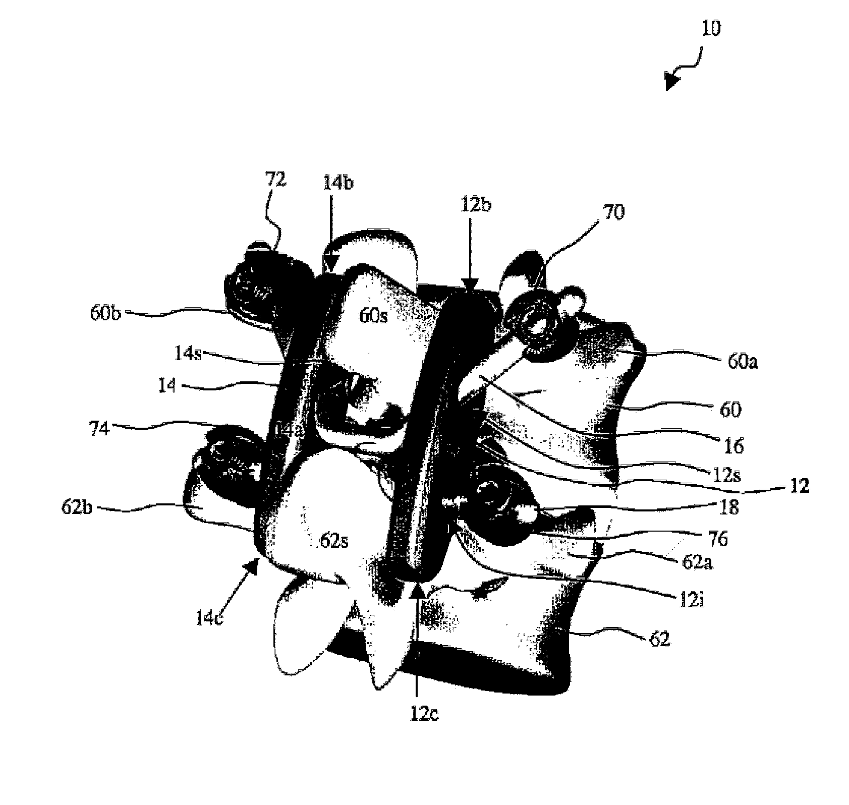
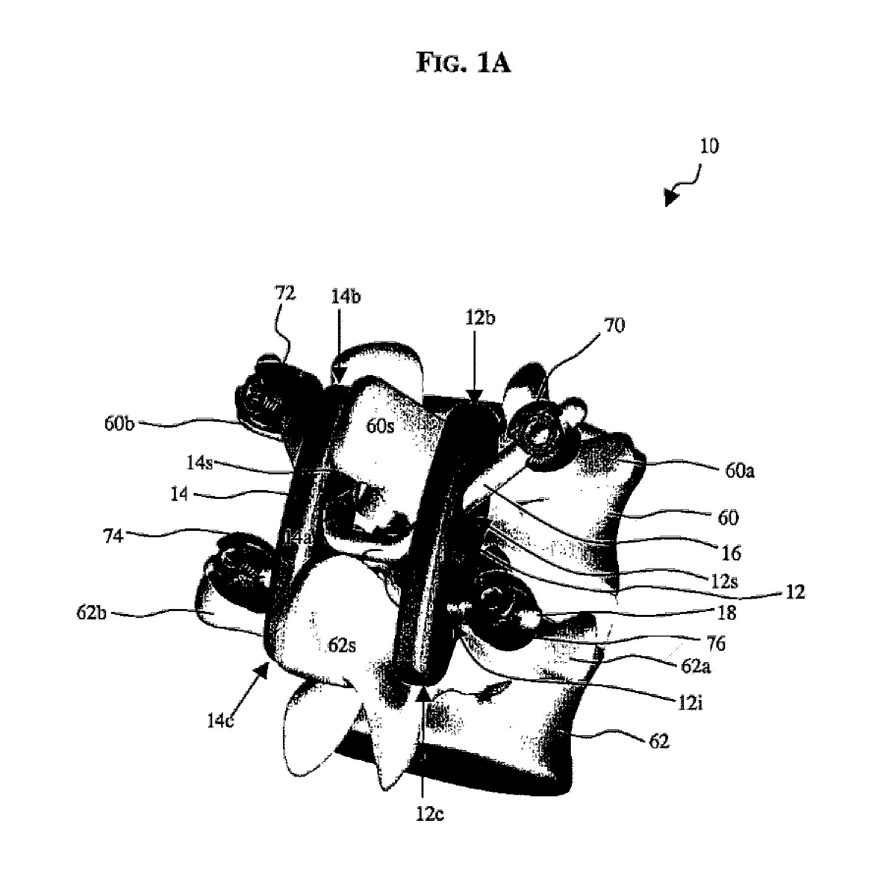
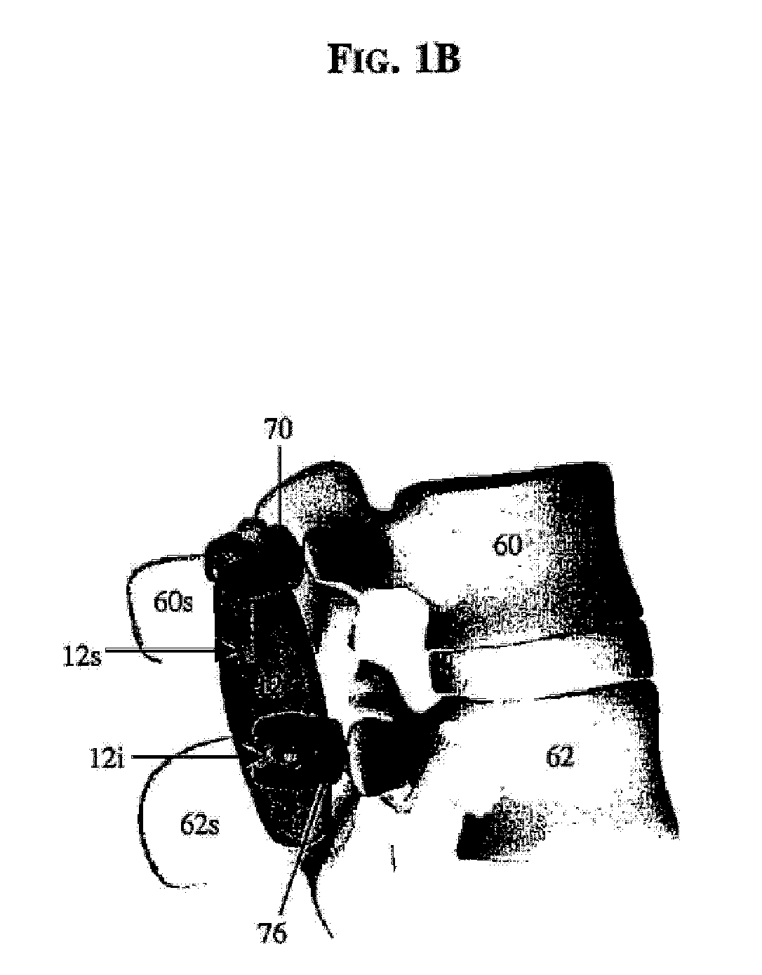
[0046] The present invention provides various methods and devices for stabilizing the posterior elements of the spine, and more preferably for sharing the load with the intervertebral disc, the face...


PUM


Abstract

A posterior stabilization device is provided for controlling movement between adjacent vertebrae. In one exemplary embodiment, the stabilization device can include one or more joints that rely on rotational or sliding movement to allow flexion of adjacent vertebrae, and that control extension, lateral bending, axial rotation, and anterior-posterior shear, preferably by providing one or more flexible connectors and/or a flexible central spacer for connecting to the adjacent superior and inferior vertebrae.

Description

CROSS REFERENCE TO RELATED APPLICATIONS [0001] This application is a continuation-in-part of U.S. patent application Ser. No. 10 / 955,207 filed on Sep. 30, 2004 and entitled “Posterior Stabilization Systems And Methods,” which is hereby incorporated by reference in its entirety.FIELD OF THE INVENTION [0002] The present invention relates to spinal instrumentation, and in particular to various devices that are adapted to mimic the natural function of the structural posterior elements. BACKGROUND OF THE INVENTION [0003] The vertebrae in a patient's spinal column are linked to one another by the disc and the facet joints, which control movement of the vertebrae relative to one another. Each vertebra has a pair of articulating surfaces located on the left side, and a pair of articulating surfaces located on the right side, and each pair includes a superior articular surface, which faces upward, and an inferior articular surface, which faces downward. Together the superior and inferior art...

Claims


Application Information

Patent Timeline
Patent Type & Authority Applications(United States)
IPC IPC(8): A61F2/30
CPCA61B17/7001A61B17/7023A61B17/7025A61B17/7031A61B17/7043A61B17/7049A61B2017/7073
Inventor BORGSTROM, AMIEKWAK, SEUNGKYU DANIELMOUMENE, MISSOUMDUNBAR, WILLIAMHAWKINS, JOHN RILEY
Owner DEPUY SPINE INC (US)
Why Eureka
Try Eureka