Direct type backlight unit having liftable frame structure

a backlight unit and frame structure technology, applied in the direction of instruments, lighting and heating apparatus, gas discharge lamp details, etc., can solve the problems of inconvenient disassembly or assembly work, inability to adjust the height difficulty in disassembling or assembling work, so as to reduce the thickness of the backlight unit, avoid uneven luminance problems, fixed and accurate positioning

Active Publication Date: 2005-04-28
HANNSTAR DISPLAY CORPORATION
View PDF5 Cites 30 Cited by
  • Summary
  • Abstract
  • Description
  • Claims
  • Application Information

AI Technical Summary

Benefits of technology

[0014] It is another object of the present invention to provide a LCD backlight unit, which has a plurality of lamps wherein at least one lamp has a foggy surface so as to reduce the backlight unit in thickness and avoid the uneven luminance problem presented on the liquid crystal panel.
[0015] In order to achieve the above objects, the present invention provides a direct type backlight unit having a liftable frame structure. The present direct type backlight unit comprises a housing, a reflector, a upper frame and a plurality of lamps. The reflector is disposed on the base surface of the housing. The plurality of lamps are disposed within a cavity defined by the housing and at least one lamp has a foggy region. The upper frame is configured to accommodate a plurality of optical films and a liquid crystal panel and has two clip members for engaging with two connection hole of the housing. Further, the upper frame is provided with a plurality of positioning elements and the housing is provided with a plurality of positioning holes such that the upper frame can be fixedly and accurately positioned on the housing by the connection of the positioning elements and the positioning holes. In addition, the direct type backlight unit having a liftable frame structure comprises a plurality of lamp connection unit wherein each lamp connection unit comprises a conductive clamp member for clamping the conductive electrode of the lamp, thereby facilitating the assembling and disassembling works while replacing or repairing the lamps.
[0016] According to the direct type backlight unit of the present invention, the upper frame is fixed on the housing by the clip members and thus can be easily disassembled from the housing without using any tools while the lamps will be repaired or replaced. Also, since the plurality of optical films and the liquid crystal panel are accommodated within the upper frame, they can be removed together with the upper frame while the upper frame is disassembled from the housing. In this manner, the plurality of optical films and the liquid crystal panel will not be separated and polluted so as to facilitate the assembling and disassembling works while replacing or repairing the lamps.
[0017] In addition, according to the direct type backlight unit of the present invention, each lamp connection unit has a clamp member which is electrically connected to a power and electrically clamps the conductive electrode of the lamp so as to light up each lamp. In this configuration, the lamp can be electrically connected to a power without using conventional soldering process. Also, the lamp can be easily replaced without using any auxiliary tools.
[0018] Further, since the lamp of the backlight unit according to the present invention has the foggy region, the distance between the liquid crystal panel and the lamp can be reduced without causing bright lines and dark lines on the liquid crystal panel, i.e. without causing the uneven luminance problem. Therefore, the backlight unit according to the present invention can be reduced so as to make the liquid crystal display device thinner.

Problems solved by technology

Therefore, these removal steps might cause a difficulty in disassembling or assembling work.
However, the connection structure of the liquid crystal display device disclosed by Sasuga et al. is accomplished by the plurality of screws and fasteners, which is also inconvenient for disassembling or assembling work.
Furthermore, the soldering manner has tedious processing steps and lower reliability.
Also, if a defective solder is formed by a bad soldering process, the solder connecting the conductive end and the conductive line may be melted by a high temperature generated while the lamps are lit up and therefore results in short circuit.
In addition, if a solder connecting the conductive end and the conductive line is not well isolated, it may generate point discharge and thus causes scorch or leakage problems.
However, if the distance between the liquid crystal panel and the lamps is too close, there will exist uneven luminance problem, i.e., bright lines and dark lines presented on the liquid crystal panel.
Also, if the distance between the liquid crystal panel and the lamps is increased, the whole thickness of the liquid crystal display device will become larger.
Further, if the distance between the liquid crystal panel and the lamps is too far, the luminance of the liquid crystal panel might be decreased to result in inefficient light utilization.

Method used


Image

  • Direct type backlight unit having liftable frame structure
  • Direct type backlight unit having liftable frame structure
  • Direct type backlight unit having liftable frame structure

Examples


Embodiment Construction

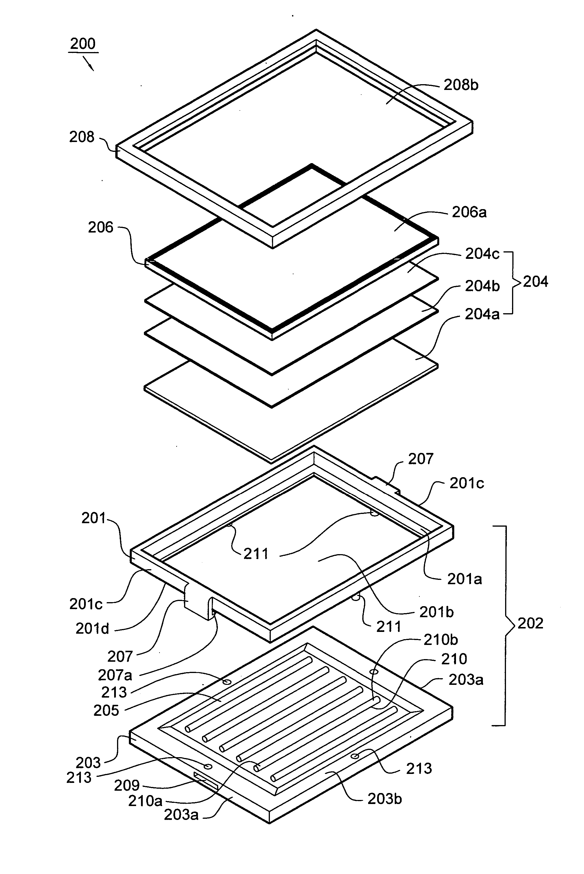
[0041]FIG. 4 is an exploded view of a liquid crystal display device 200 according to one embodiment of the present invention. The liquid crystal display device 200 comprises a direct type backlight unit 202, a set of optical films 204, a liquid crystal panel 206 and an outer frame 208. The liquid crystal panel 206 is used for producing an image and the direct type backlight unit 202 is used for emitting light to the liquid crystal panel 206. The set of optical films 204 is disposed between the backlight unit 202 and the liquid crystal panel 206. The set of optical films 204 includes a diffuser 204a disposed upon the backlight unit 202 and a plurality of optical sheets, such as a diffusing sheet 204b and a prism sheet 204c, disposed on the diffuser 204a. The diffuser 204a is disposed upon the backlight unit 202 and typically made of half-transparent polyethylene terephthalate (PET), polyethylene terephthalate (PC), or polycarbonate for further evenly diffusing the light emitted from ...


PUM

PropertyMeasurementUnit
diameteraaaaaaaaaa
diameteraaaaaaaaaa
diameteraaaaaaaaaa

Abstract

A direct type backlight unit having liftable frame structure comprises a housing, an upper frame and a plurality of lamps, wherein the plurality of lamps disposed on a cavity defined by the housing and at least one has a foggy region; the upper frame is configured to accommodate a plurality of optical films and a liquid crystal panel and has two clip members for engaging with two connection hole of the housing such that the upper frame can be easily fixed on the housing. A plurality of lamp connection units are disposed within the cavity and each comprises a conductive clamp member for clamping the conductive electrode of the lamp, thereby facilitating the replacement of the lamps.

Description

[0001] This application claims the priority benefit of Taiwan Patent Application Serial Number 092130637 filed Nov. 3, 2003, Taiwan Patent Application Serial Number 093100504 filed Jan. 9, 2004 and Taiwan Patent Application Serial Number 093100505 filed Jan. 9, 2004, the full disclosures of which are incorporated herein by reference. BACKGROUND OF THE INVENTION [0002] 1. Field of the Invention [0003] This invention generally relates to a direct type backlight unit, and more particularly to a direct type backlight unit having a liftable frame structure. [0004] 2. Description of the Related Art [0005] In general, a liquid crystal display typically has a backlight unit for providing light needed by its liquid crystal panel. However, the liquid crystal display may use different kinds of backlight units depending on its use and size. The backlight units mainly include two types, i.e. an edge type and a direct type. [0006] Due to the advantages of high luminance, high light efficiency and...

Claims


Application Information

Patent Timeline
Patent Type & Authority Applications(United States)
IPC IPC(8): G02F1/13G02F1/13357H01J61/34H01J61/35
CPCG02F1/133604H01J61/35H01J61/34
Inventor HUANG, HSIN FUCHEN, CHIN JING
Owner HANNSTAR DISPLAY CORPORATION
Why Eureka
Try Eureka