
Dispenser for Rolled, Perforated, Folded, and/or Interwoven Bags, Wipes and Other Flexible Dispensible Materials

a technology for dispensing materials and dispensers, which is applied in the direction of packaging, transportation and packaging, internal fittings, etc., can solve the problems of dispense too much material, break material, and prior art dispensers lack a mechanism to slow down the dispensing of material, so as to manage the speed, and slow down the dispensing

Active Publication Date: 2017-12-14
DIVERGENT DEVICES LLC
View PDF2 Cites 0 Cited by
  • Summary
  • Abstract
  • Description
  • Claims
  • Application Information

AI Technical Summary

Benefits of technology

The present invention is a dispensing device that allows for controlled and safe dispensation of material without breaking or overdispensing. It includes a mechanism to slow down the dispensation and prevent the material from getting tangled or overtightened. The device also keeps the next item in place, making it convenient for the user to hold the material and keep it for the next time it is needed. Additionally, the device helps in breaking the material after it exits the container, eliminating the need for a separate tearing device. This avoids inaccurate tearing of the material and ensures consistent and safe dispensing.

Problems solved by technology

In the prior art, the speed and force of the user pulling the material will often either break the material or will dispense too much of the material.
Dispensers in the prior art lack a mechanism to slow the dispensation of the material to prevent breaking or over dispensing.
Unfortunately, such attempts to use tearing devices on dispensers in the prior art results in a perforation staying intact and / or a tear in the material in the wrong place.
In the case of plastic bags, which are the typical composition of waste disposal bags, the inaccurate tearing process ruins the bags in the prior art.
Accordingly, dispensing devices in the prior art cannot be handheld in a single hand, since the user must often use two hands to grasp portions of the exposed material on either side of a perforation, in order to attempt to accurately tear the material at the perforation.
Furthermore, in the prior art, such dispensing devices, with or without tearing devices, often do not hold the next item for dispensing in a consistent, predictable and reachable position.

Method used


Image

  • Dispenser for Rolled, Perforated, Folded, and/or Interwoven Bags, Wipes and Other Flexible Dispensible Materials
  • Dispenser for Rolled, Perforated, Folded, and/or Interwoven Bags, Wipes and Other Flexible Dispensible Materials
  • Dispenser for Rolled, Perforated, Folded, and/or Interwoven Bags, Wipes and Other Flexible Dispensible Materials

Examples


first embodiment

[0052]FIGS. 8-9 show a dispenser 70 of the present invention, which has the faceplate 14 with aperture 18 and slot 34, and an upper surface 72 with a guide member 74 extending downward into the interior of the dispenser 70 to guide the material 12 in a manner as described in connection with the guide member 58 shown in FIGS. 6-7. The guide member 74 may be attached and secured to the underside of the upper surface 72 by adhesive, welding, or other fastening or attaching mechanism.

[0053]FIGS. 10-11 show an alternative configuration of the first embodiment of FIGS. 8-9, in which the guide member 74 is formed by folding the upper surface 72 instead of attaching a separate member to the upper surface 72 as the guide member 74. Accordingly, a crease 76 or other indentation in the upper surface 72 may result. In addition, the upper surface 72 may be attached to the other members of the dispenser 70 with a hinge 78 to facilitate opening the dispenser 70 to replace rolls of material 12 ther...

third embodiment

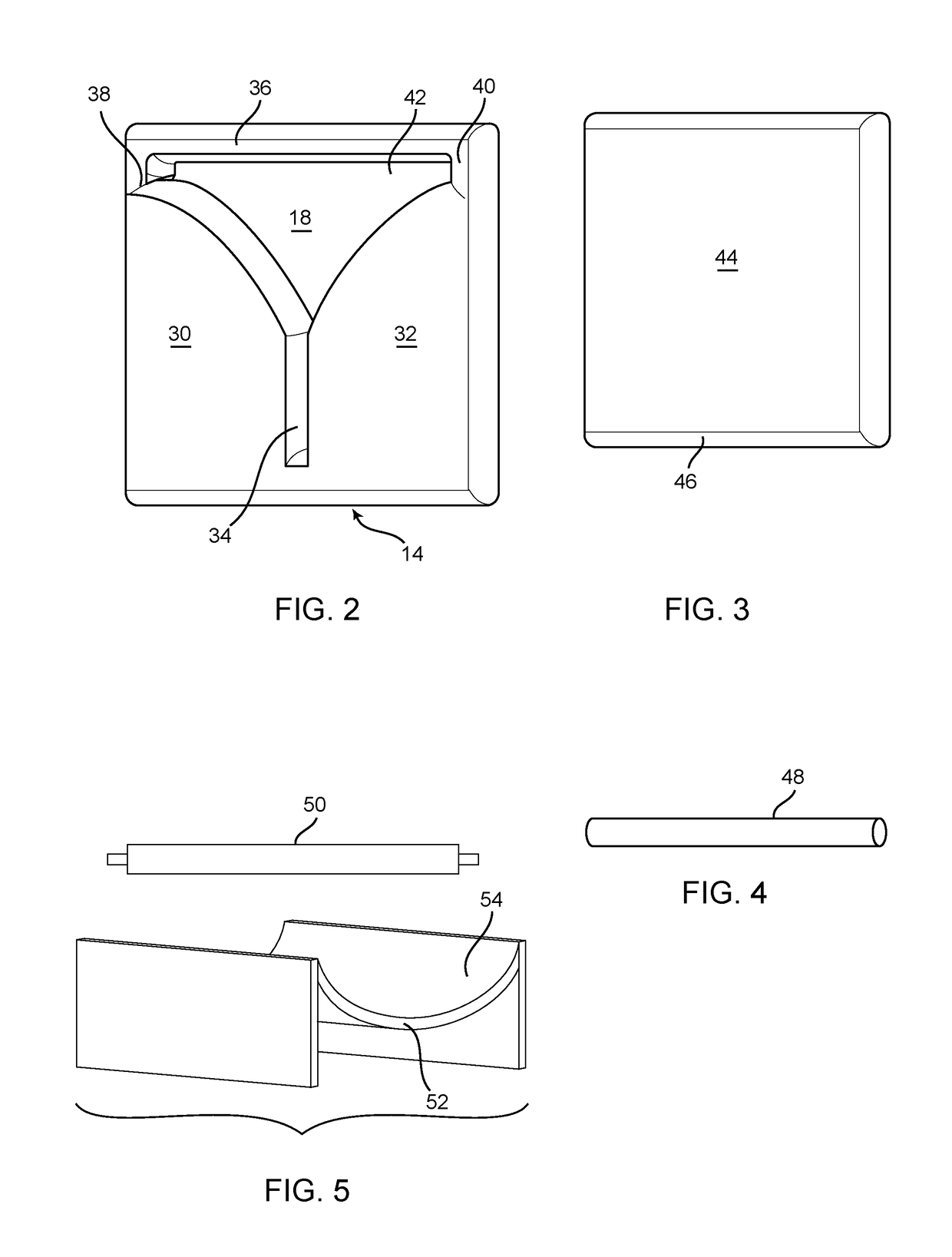
[0054]FIGS. 12-14 show a dispenser 80 of the present invention, in which the faceplate 14, having the aperture 18 and slot 34, is attached via hinges 82 to an upper faceplate 84, allowing the faceplate 14 to be rotated to open the dispenser 80 for replace rolls of material 12 therein. Optionally, the dispenser 80 may include at least one arm mechanism 86 to releasably secure the faceplate 14 in an open configuration as shown in FIG. 14, allowing for ease of replacement of rolls of material 12 while the faceplate 14 is in the open configuration. Although not shown, a guide 48 such as that shown in FIG. 4 secures the material 12 at a bottom portion of the dispenser 80 and provides sufficient tension to the material 12 when the material free end 16 is pulled by the user.

fourth embodiment

[0055]FIGS. 15-17 show a dispenser 90 of the present invention, which has a generally cylindrical shape, including a faceplate 92 having a curved shape matching the curvature of other portions of the dispenser 90. Alternatively, the faceplate 92 forms the cylindrical sides of the dispenser 90, with the substantially triangular aperture 18 therethrough, and substantially planar side caps 94, 96. Internal to the dispenser 90, as shown in FIG. 17, at least one guide member 98, 100 is disposed to form a cradle for the roll of material 12, and to provide tension and guide the material 12 to the aperture 18. The dispenser 90 may also be dimensioned to be handheld.


PUM


Abstract

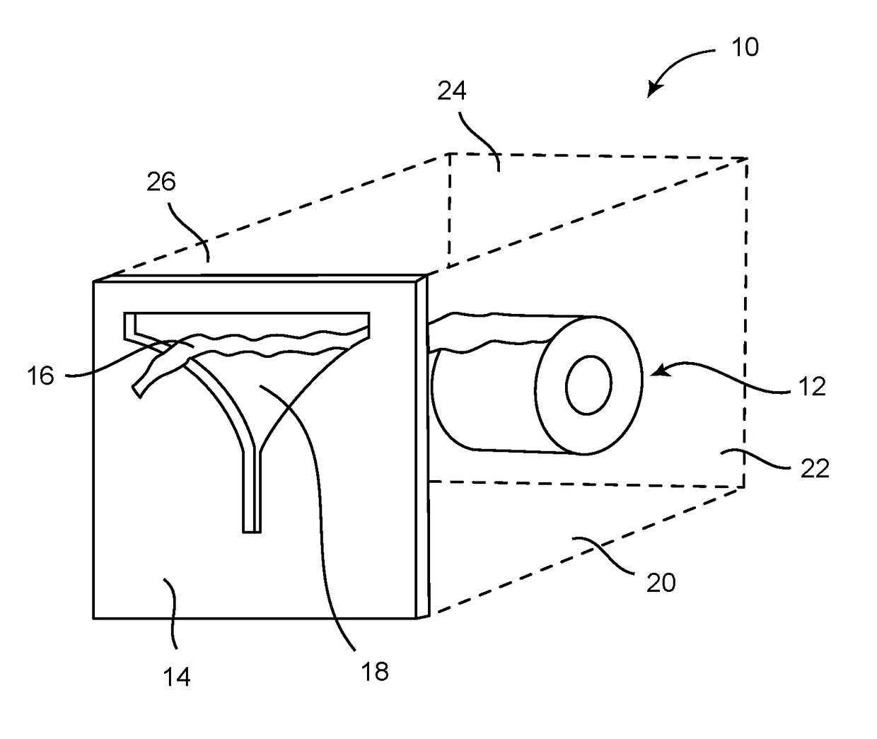
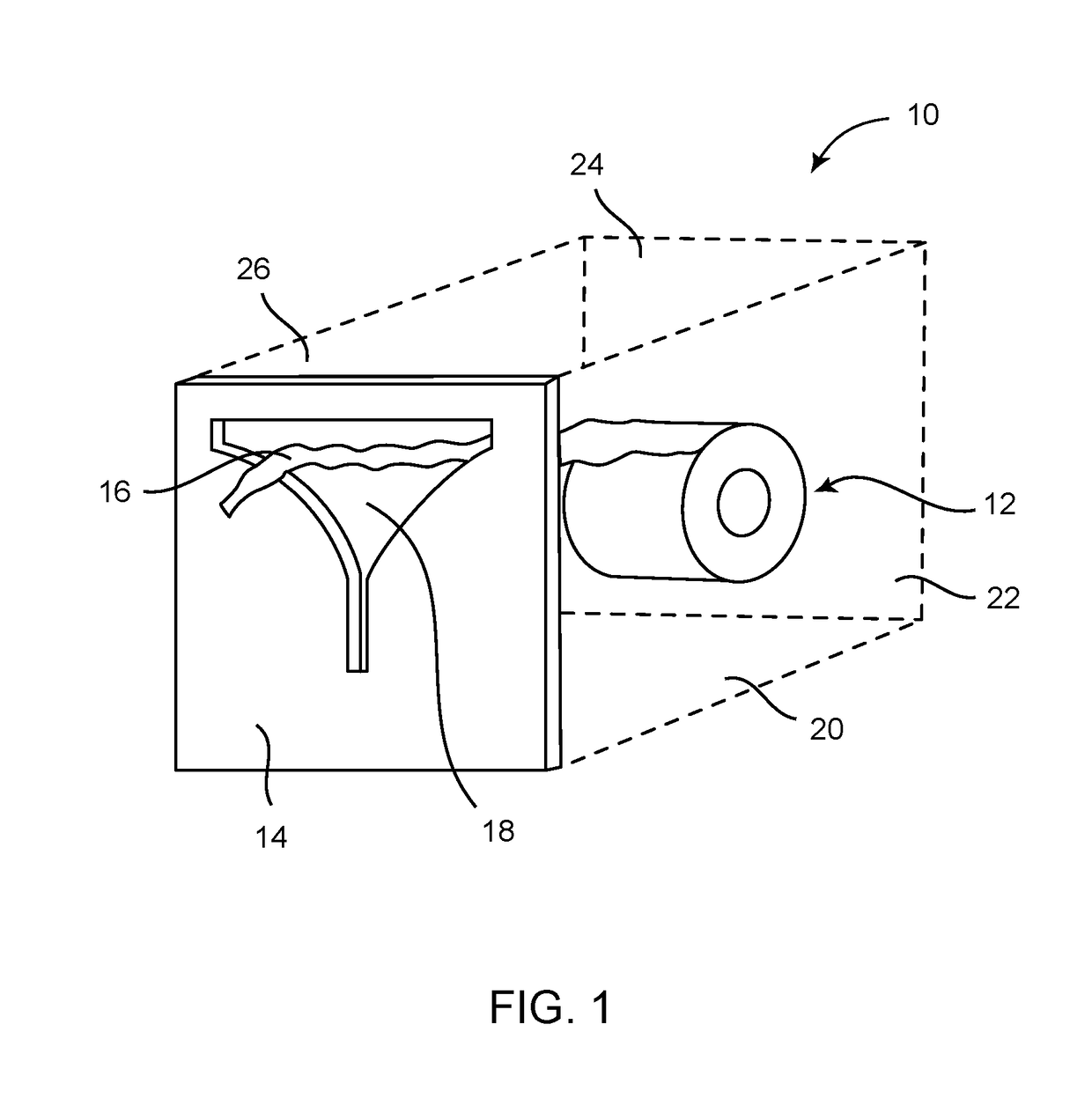
A dispensing device includes a container retaining a dispensable material, which prevents the material from breaking prior to being dispensed or over-dispensing material by including a mechanism to slow the dispensation of the material, and also aids in breaking the material subsequent to the material exiting the container. The container has a faceplate with at least three members forming a substantially triangular aperture through which the dispensable material is fed. The three members include a pair of opposing flanges forming the triangular aperture therebetween. The pair of opposing flanges further form a substantially linear slot therebetween and contiguous with the triangular aperture, with the dispensable material further fed through the slot. Each of the pair of opposing flanges has a curved surface forming a side of the triangular aperture.

Description

CROSS-REFERENCE TO RELATED APPLICATION[0001]This application claims priority to U.S. Provisional Application No. 62 / 348,685, filed on Jun. 10, 2016, which is incorporated by reference in its entirety.BACKGROUND OF THE INVENTION1. Field of the Invention[0002]The present invention relates to a dispenser of materials, and in particular to a dispenser for rolled, perforated, folded, and / or interwoven bags, paper towels, toilet paper, wipes, and other flexible dispensable materials.2. Description of Prior Art[0003]Dispensers in the form of containers are known in the art to have a single, generally rectangular slot through which paper towels, toilet paper, waste disposal bags, and the like are fed and dispensed. Typically, a user grasps a portion of the paper towel, toilet paper or bag, and then pulls the remaining portion through the rectangular slot.[0004]In the prior art, the speed and force of the user pulling the material will often either break the material or will dispense too muc...

Claims


Application Information

Patent Timeline
Patent Type & Authority Applications(United States)
IPC IPC(8): B65D83/08B65D51/26B65D25/10B65D43/16B65D85/672
CPCB65D83/0805B65D85/672B65D51/26B65D43/163B65D25/10A47K10/38
Inventor ATALLA, ELIE
Owner DIVERGENT DEVICES LLC
Learn More