
Eureka
For R&D, Eureka makes reading and utilizing patents & technical documents easy.
Eureka AIR
Designed for self-driven R&D workflows. Generate viable solutions, solve complex R&D challenges, empower your innovation with AI.

Eureka Materials
Designed for material experts only. Revolutionize your material R&D, from search, analyze, to developing new materials.

TechResearch
Generate reliable direction feasibility study reports for your R&D in just a few steps.

TechSeek
Discover and master advanced knowledge NOW. Basics, ideas, possibilities, all at once.

TechMind
As an expert in R&D Theories, TechMind can generates customized viable solutions instantly.

TechRisk
Analyze your overall solution with one click, know your potential R&D risks in advance.

TechMonitor
Get weekly tech updates, stay abreast of the latest tech innovations and key insights.
Vehicle air-conditioning device
- Summary
- Abstract
- Description
- Claims
- Application Information
AI Technical Summary
Benefits of technology
Problems solved by technology
Method used
Image

Examples
first embodiment
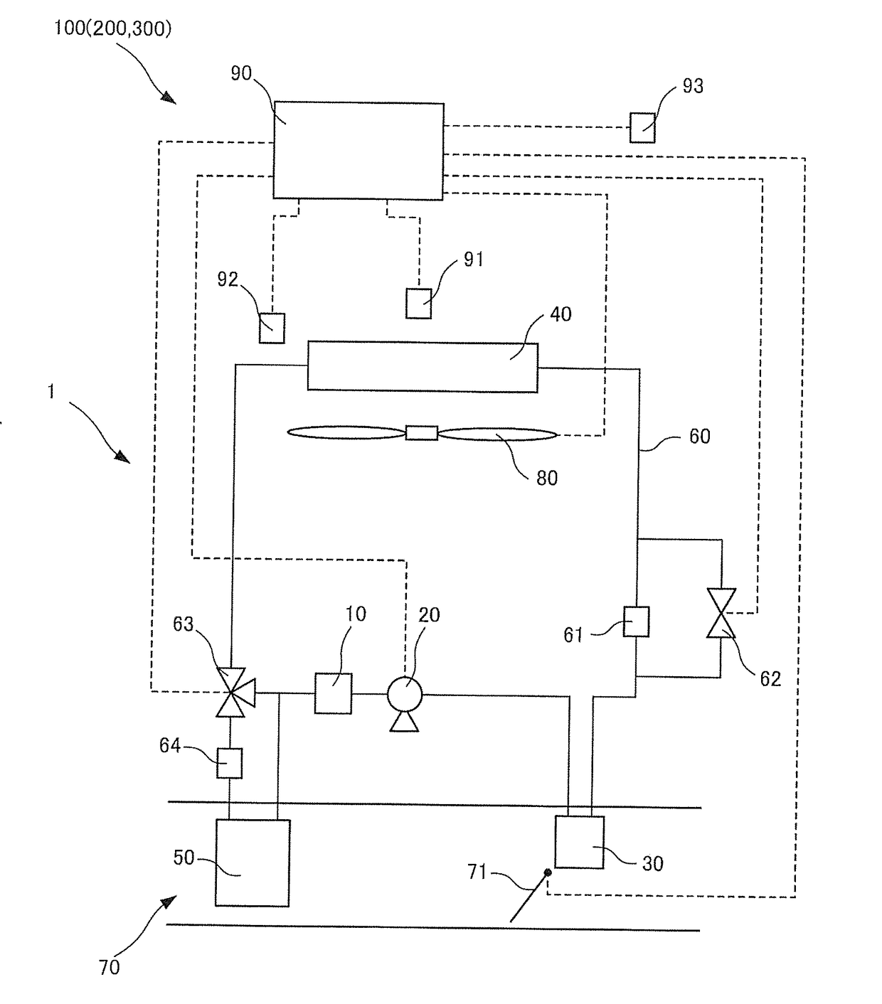
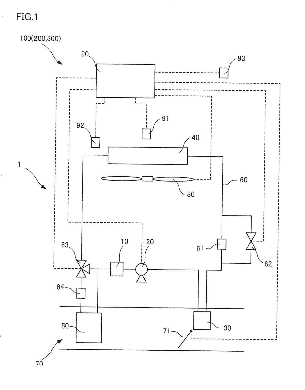
[0015]FIG. 1 is a system configuration diagram of a vehicle air-conditioning device 100 according to a first embodiment of the present invention.
[0016]The vehicle air-conditioning device 100 includes a heat pump cycle 1, an HVAC unit (Heating Ventilation and Air Conditioning Unit) 70, and a controller 90.
[0017]The heat pump cycle 1 includes a refrigerant flow path 60 through which refrigerant flows, an accumulator 10 that is provided in the refrigerant flow path 60 and performs gas / liquid separation of the refrigerant, a compressor 20 that compresses the refrigerant, a condenser 30 that releases heat of the high-pressure refrigerant, an external heat exchanger 40 that performs heat exchange between the refrigerant and the outside air, and an evaporator 50 that causes the heat of the surrounding air to be absorbed into the refrigerant. As the refrigerant, for example, HFC-134a etc. is used.
[0018]The accumulator 10 performs gas / liquid separation on the refrigerant flowing through the ...
second embodiment
[0064]A vehicle air-conditioning device 200 according to a second embodiment of the present invention will be described with reference to FIG. 6. FIG. 6 is a flowchart of the frost-formation determination control executed by the controller 90 of the vehicle air-conditioning device 200. The flowchart in the second embodiment differs from that in the first embodiment in that a degree of frost formation F is estimated from the frost-formation time tf, and a frost-formation determination is executed on the basis of the degree of frost formation F. In the following embodiments, components having the same function as those in the first embodiment are assigned the same reference signs, and explanation will be made by appropriately omitting repetitive descriptions.
[0065]In Steps S301 to S303, the controller 90 performs the processes that are the same as those of Steps S101 to S103 in the first embodiment. In the case in which the heating operation is determined as ON in Step S301, the contr...
third embodiment
[0079]A vehicle air-conditioning device 300 according to a third embodiment of the present invention will be described with reference to FIG. 7. FIG. 7 is a flowchart of the frost-formation determination control executed by the controller 90 of the vehicle air-conditioning device 300. In the flowchart in the third embodiment differs from those in the first embodiment and the second embodiment in that the frost-formation determination is executed by calculating an accumulated degree of frost formation S from the degree of frost formation F estimated.
[0080]In Step S401, the controller 90 performs the process that is the same as that of Step S101 in the first embodiment, and in the case in which the heating operation is ON, executes the process of Step S402.
[0081]In Step S402, the controller 90 reads out an initial accumulated degree of frost formation Sini from the RAM. The initial accumulated degree of frost formation Sini represents the integrated value of the degree of frost format...
PUM
 Abstract
Description
Claims
Application Information
 - R&D Engineer
- R&D Manager
- IP Professional
- Industry Leading Data Capabilities
- Powerful AI technology
- Patent DNA Extraction
Browse by: Latest US Patents, China's latest patents, Technical Efficacy Thesaurus, Application Domain, Technology Topic, Popular Technical Reports.
© 2024 PatSnap. All rights reserved.Legal|Privacy policy|Modern Slavery Act Transparency Statement|Sitemap|About US| Contact US: help@patsnap.com