
Collision detection apparatus, collision determination method, and activation control apparatus for occupant protection apparatus

a technology for determining apparatus and occupant protection, which is applied in the direction of process and machine control, pedestrian/occupant safety arrangement, instruments, etc., can solve the problems of determining delay and occurrence of delay in timing, and achieve the effect of accurate determination

Inactive Publication Date: 2014-12-30
TOYOTA JIDOSHA KK +2
View PDF16 Cites 0 Cited by
  • Summary
  • Abstract
  • Description
  • Claims
  • Application Information

AI Technical Summary

Benefits of technology

This invention is about a device and method that can detect when a person or object collides with the exterior or interior of a vehicle door. The device measures the acceleration in the direction of the door, and if it exceeds a certain threshold value, the device starts to integrate the acceleration. This allows the device to accurately determine if a collision has occurred. The detected acceleration is also used to determine if the occupant protection apparatus should be activated to prevent unnecessary operations and protect the occupants from injury. Overall, this invention helps to quickly and accurately detect collisions with vehicle doors and take appropriate action to prevent accidents.

Problems solved by technology

However, in the collision detection apparatus described in Japanese Patent Application Publication No. 2009-090717 (JP-A-2009-090717), when a vehicle is traveling on a rough road, or when a door portion is closed hard, or the like, there is possibility of occurrence of a delay in the timing of determining that an object has collided with the door portion of the vehicle from outside, due to effect of an integral of the acceleration that occurs on the door portion.
Thus, there occurs a delay in the timing of determining that an object has collided with the door portion from outside (see FIG. 15).

Method used


Image

  • Collision detection apparatus, collision determination method, and activation control apparatus for occupant protection apparatus
  • Collision detection apparatus, collision determination method, and activation control apparatus for occupant protection apparatus
  • Collision detection apparatus, collision determination method, and activation control apparatus for occupant protection apparatus

Examples


first embodiment

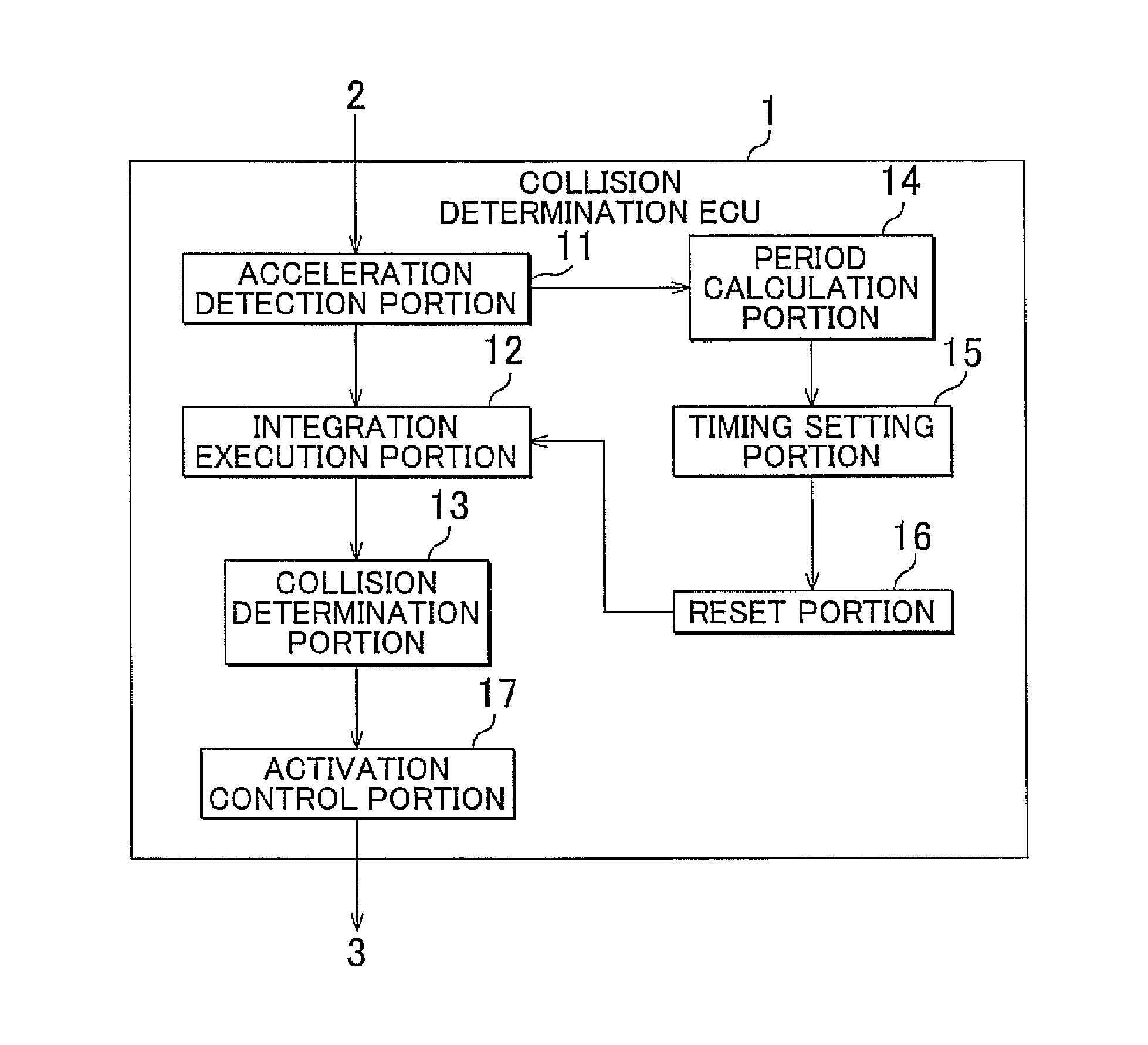
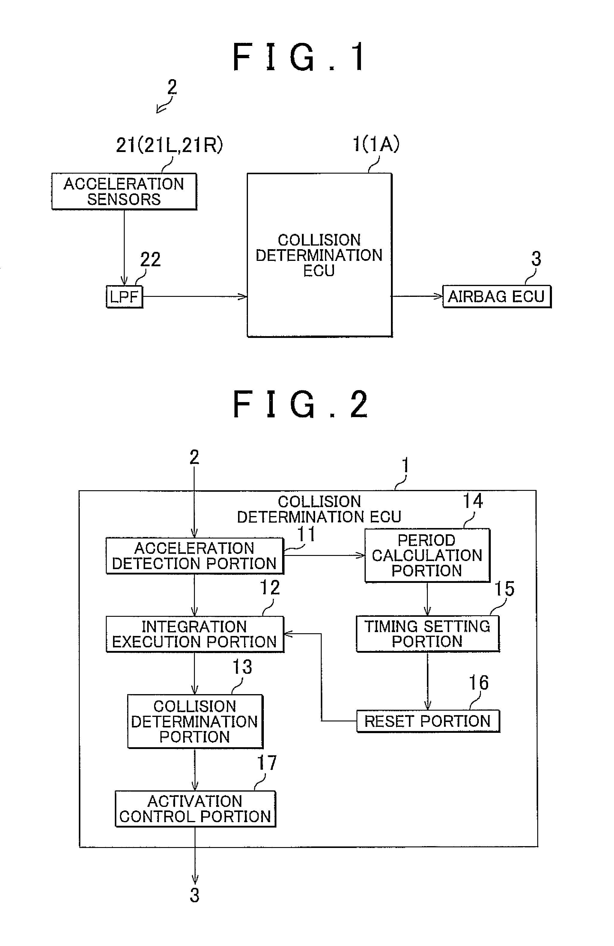
[0051]FIG. 2 is a block diagram showing an example of a functional construction of the collision determination ECU 1 in accordance with the As shown in FIG. 2, the collision determination ECU 1 includes an acceleration detection portion 11, an integration execution portion 12, a collision determination portion 13, a period calculation portion 14, a timing setting portion 15, a reset portion 16, and an activation control portion 17.

[0052]Incidentally, the collision detection apparatus in accordance with the invention corresponds to the acceleration detection portion 11, the integration execution portion 12, the collision determination portion 13, the period calculation portion 14, the timing setting portion 15 and the reset portion 16 of the collision determination ECU 1. The activation control apparatus for an occupant protection apparatus in accordance with the invention corresponds to the acceleration detection portion 11, the integration execution portion 12, the collision deter...

second embodiment

[0100]Although the second embodiment has been described above in conjunction with the construction in which the timing setting portion 15A sets the reset timing at a timing that is later the larger the absolute value GPA of the negative peak value GP of the acceleration GR is, it suffices that the timing setting portion 15A sets the reset timing on the basis of the acceleration GR. For example, the timing setting portion 15A may set the reset timing at a time at which a pre-set reset period elapses, when the acceleration GR becomes less than or equal to a pre-set threshold value (2). In this construction, the process is simplified.

[0101]FIG. 13 is a flowchart showing an example of actions of the collision determination ECU 1A in accordance with the second embodiment. Firstly, the acceleration detection portion 11 of the collision determination ECU 1A detects the acceleration GR via the acceleration sensors 21 and the LPF 22 (S301). Then, the integration execution portion 12 determin...


PUM


Abstract

A collision detection apparatus that is mounted in a vehicle and that determines whether an object has collided with a side surface of the vehicle from outside the vehicle includes: an acceleration detection portion that detects acceleration in a transverse direction of the vehicle which is applied to a door portion of the vehicle from outside; an integration execution portion that starts integration of the acceleration detected by the acceleration detection portion and finds velocity by integrating the acceleration if the detected acceleration is greater than or equal to a pre-set positive first threshold value, or is less than or equal to a pre-set negative second threshold value; and a collision determination portion that determines whether an object has collided with a side surface of the vehicle based on the detected acceleration and the velocity found by the integration execution portion.

Description

INCORPORATION BY REFERENCE[0001]The disclosure of Japanese Patent Application No. 2009-124449 filed on May 22, 2009 including the specification, drawings and abstract is incorporated herein by reference in its entirety.BACKGROUND OF THE INVENTION[0002]1. Field of the Invention[0003]The invention relates to a collision detection apparatus that is, for example, mounted in a vehicle, and that determines whether an object has collided with a side surface of the vehicle from outside, and to a collision determination method therefore. Besides, the invention also relates to an activation control apparatus for an occupant protection apparatus which is, for example, mounted in a vehicle, and which determines whether an object has collided with a side surface of the vehicle from outside, and which controls activation of the occupant activation device.[0004]2. Description of the Related Art[0005]In order to appropriately protect an occupant of a vehicle by an occupant protection apparatus, suc...

Claims


Application Information

Patent Timeline
Patent Type & Authority Patents(United States)
IPC IPC(8): G06F19/00B60R21/0132B60R21/16B60R21/0136B60R21/00
CPCB60R2021/0006B60R2021/0009B60R21/0132B60R21/0133B60R21/01336B60R2021/01322
Inventor MASE, YUSUKEIYODA, MOTOMINAGAO, TOMOKITAKEUCHI, HIROYOSHITANIGUCHI, SUGURU
Owner TOYOTA JIDOSHA KK
Learn More