Depth-Adjustable Steering Column Mechanism with a Retractable Stop

a technology of depth adjustment and steering column, which is applied in the direction of steering column, steering control, vehicle mounted steering control, etc., can solve the problems of limiting the transmission to the interlock and the locking mechanism, and achieve the effect of increasing the resistance to retraction of the column and minimising noise and friction

Active Publication Date: 2017-12-21
ROBERT BOSCH AUTOMOTIVE STEERING VENDOME SAS
View PDF1 Cites 8 Cited by
  • Summary
  • Abstract
  • Description
  • Claims
  • Application Information

AI Technical Summary

Benefits of technology

[0019]According to an alternative embodiment, the locking mechanism releases the retractable stop when it moves from the unlocked position to the locked position, but does not drive it to the retracted position. Under these circumstances, the retractable stop is advantageously maintained in the active position, for example by means of a spring. The upper tube is provided with a plunger interacting with a receiving face of the retractable stop, serving to drive the retractable stop to the retracted position when the locking mechanism is in the locked position and a force exceeding a predetermined threshold is applied to the upper tube and drives the upper tube along the extension and retraction path in the direction of retraction. In practice, the plunger or the receiving face forms a ramp allowing transmission of the movement of the upper tube to the retractable stop. The advantage of this solution lies in avoiding any movement of the retractable stop durin

Problems solved by technology

This therefore limits transmission to the interlock and to the locking mechanis

Method used


Image

  • Depth-Adjustable Steering Column Mechanism with a Retractable Stop
  • Depth-Adjustable Steering Column Mechanism with a Retractable Stop
  • Depth-Adjustable Steering Column Mechanism with a Retractable Stop

Examples


Embodiment Construction

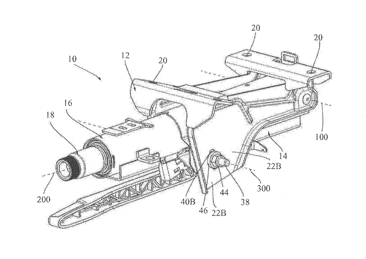
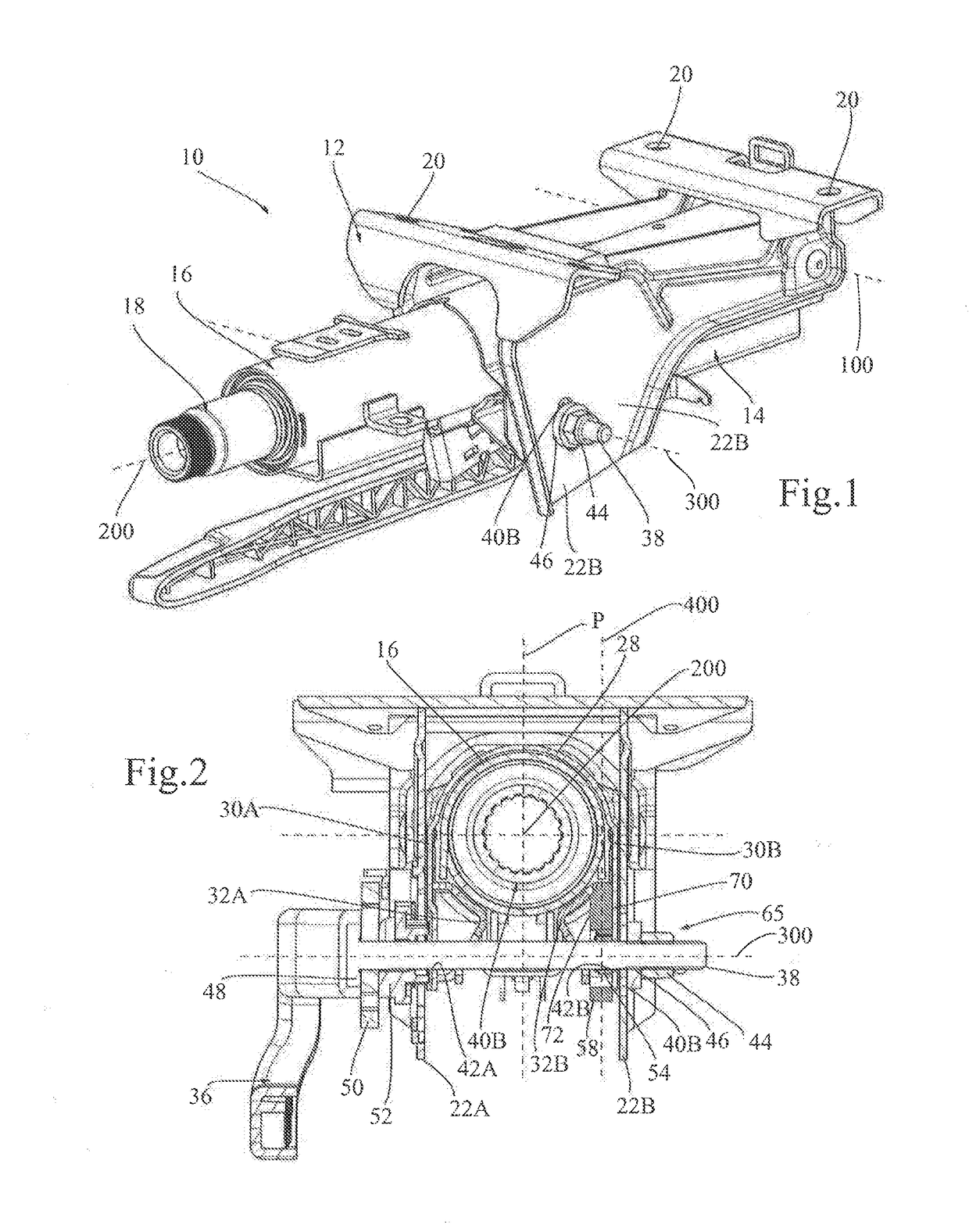
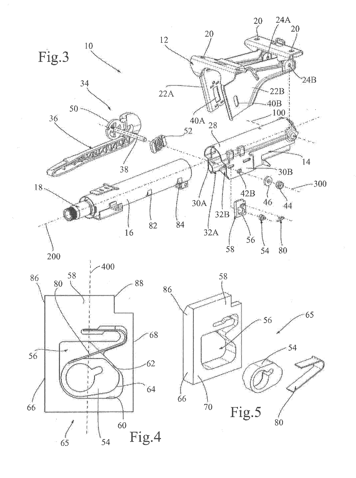
[0055]FIGS. 1 to 3 illustrate a steering column 10 for a motor vehicle, including a fixed support 12 and a movable subassembly, comprising a lower body 14 pivoting relative to the fixed support 12 around a pivot axis 100 and an upper tube 16 that serves as a housing and for rotational guiding for an endpiece of a steering shaft 18 rotating around an axis of rotation 200 perpendicular to the pivot axis 100 and preferably intersecting the latter. In a manner known per se, the upper tube 16 slides in the lower body 14 along a straight path parallel to a geometrical adjustment axis that is fixed relative to the lower body 14, which is in line with the axis of rotation 200 of the endpiece of the steering shaft 18. It is furthermore possible to define a longitudinal median plane P containing the axis of rotation and adjustment 200 perpendicular to the pivot axis 100.

[0056]The fixed support 12, preferably made in one piece or by machine-welded assembly, comprises two attachment plates for ...


PUM


Abstract

A steering column mechanism (10) comprises a lower body (14), an upper tube (16) that is movable depthwise relative to the lower body (14) along an extension and retraction path, in a direction of retraction and in a direction of extension opposite the direction of retraction, and a locking mechanism (34) for locking the upper tube (16) relative to the lower body (14), movable between a locked position and an unlocked position. A retractable stop (58) is movable relative to the lower body (14) and relative to the locking mechanism (34) between an active position and a retracted position. In the active position, the retractable stop (58) limits the travel of the upper tube (16) in the direction of retraction to an adjustment stop position, whereas in the retracted position, it does not interfere with the upper tube (16). The retractable stop (58) is linked to the locking mechanism via an interlock (65) in such a way as to be in the active position when the locking mechanism (34) is in the unlocked position. The lower body (14) comprises one or more supports (76, 78, 96) for at least partially taking up forces generated by the upper tube (16) on the retractable stop (58) when the locking mechanism (34) is in the unlocked position and the upper tube (16) is in the adjustment stop position in abutment against the retractable stop (58). Preferably, the lower body is provided with guide means (74, 76, 78, 90) for guiding the retractable stop between the retracted position and the active position.

Description

TECHNICAL FIELD OF THE INVENTION[0001]The invention relates to a steering column that is adjustable in depth and if appropriate, in height.PRIOR ART[0002]A vehicle steering column mechanism usually comprises a mobile subassembly comprising a lower body and an upper tube that is movable depthwise relative to the lower body along an extension and retraction path, wherein the upper tube has a stroke limited in the direction of retraction by a retraction stroke end stop defining a retraction stroke end position of the upper tube relative to the lower body and limited in a direction of extension by an extension stroke end stop defining an extension stroke end position relative to the lower body. A locking mechanism, movable between a locked position and an unlocked position locks the upper tube relative to the lower body. An intermediate stop limits the stroke of the upper tube in the direction of retraction to an intermediate adjustment stroke end position between the retraction stroke ...

Claims


Application Information

Patent Timeline
IPC IPC(8): B62D1/184B62D1/19B62D1/185
CPCB62D1/184B62D1/192B62D1/185
Inventor CHARVET, WILLIAMBERNIER, JACQUESSAUQUET, MICKAEL
Owner ROBERT BOSCH AUTOMOTIVE STEERING VENDOME SAS
Why Eureka
Try Eureka