
Engine assembly

a technology for engines and components, applied in the direction of machines/engines, mechanical equipment, lubricant mounting/connection, etc., can solve the problem of significant power draw

Active Publication Date: 2017-12-21
FORD GLOBAL TECH LLC
View PDF10 Cites 1 Cited by
  • Summary
  • Abstract
  • Description
  • Claims
  • Application Information

AI Technical Summary

Benefits of technology

The patent text describes certain features in relation to one or more aspects or embodiments of the invention. However, these features can also be used with other aspects or embodiments of the invention. The technical effect is that this reduces unnecessary repetition and effort in the specification and allows for more efficient development and implementation of the invention.

Problems solved by technology

The oil consuming components may require a high pressure and / or flow rate of oil and hence the oil pump may draw a significant amount of power from the engine in order to operate.

Method used


Image

  • Engine assembly
  • Engine assembly
  • Engine assembly

Examples


Embodiment Construction

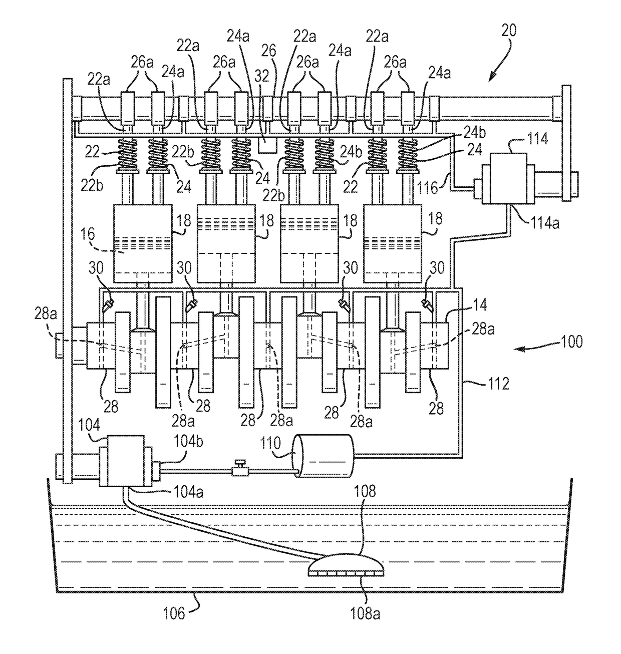
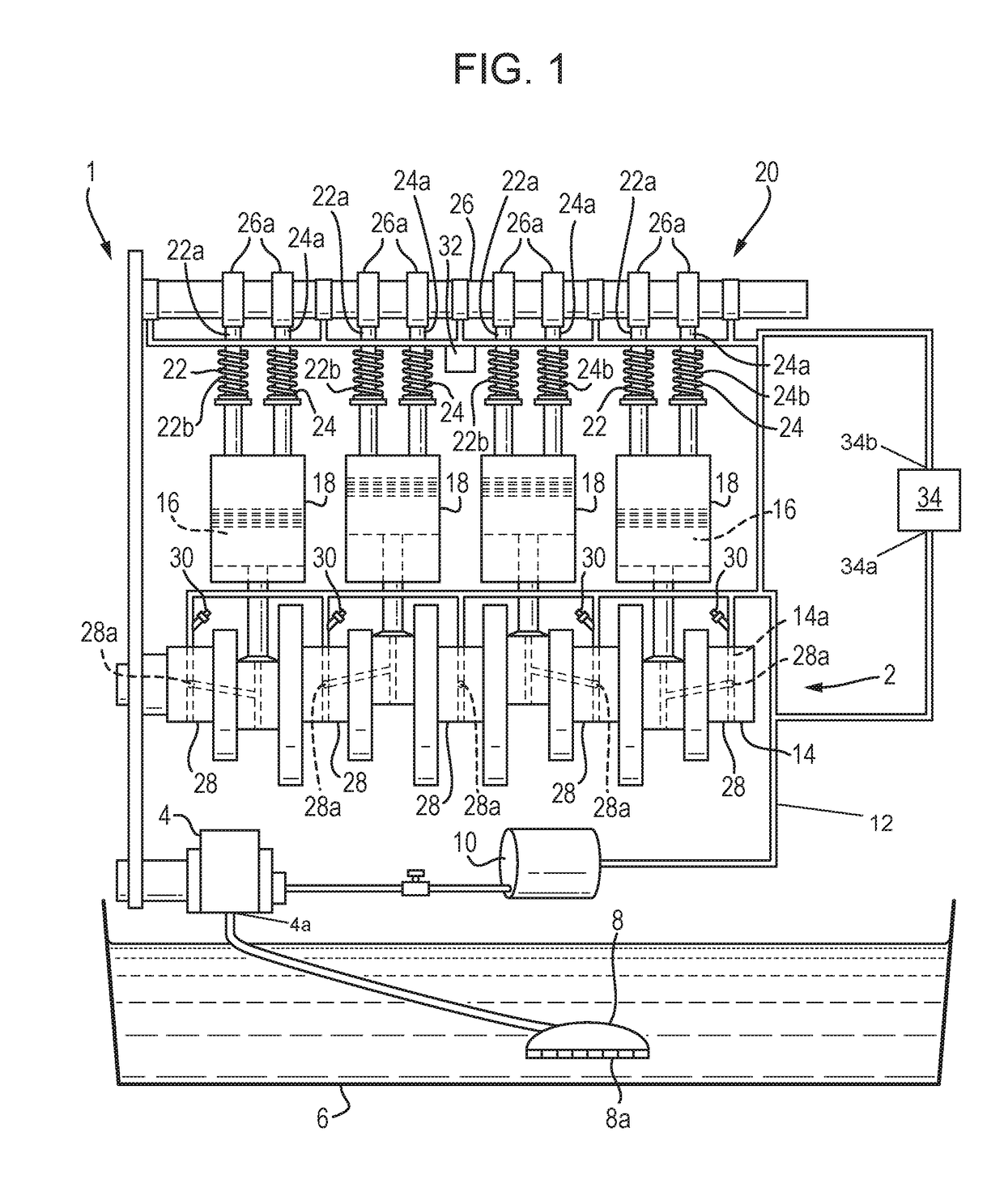
[0029]With reference to FIG. 1, an engine assembly 1 comprises an oil system 2, a crank shaft 14 and a plurality of pistons 16 configured to reciprocate within a plurality of cylinders 18. The engine assembly 1 further comprises a valve train 20 comprising a plurality of inlet and outlet valves 22, 24 and a cam shaft 26.

[0030]The inlet and outlet valves 22, 24 are configured to control the flow of inlet and exhaust gases into and out of the cylinders 18 respectively. The cam shaft 26 is configured to control the operation of the inlet and outlet valves 22, 24.

[0031]The oil system 2 comprises an oil pump 4 configured to draw oil from an oil sump 6 via an oil pick-up 8 to an inlet 4a of the oil pump. As shown in FIG. 1, the oil pump may be driven by the crank shaft 14 via a drive belt 5. The oil pick up 8 may comprise a pick-up filter 8a configured to reduce the amount of particles or debris drawn from the oil sump 6 into the oil system 2.

[0032]The oil pump 4 may be configured to pump...


PUM


Abstract

An engine assembly is provided. The engine assembly comprises an oil system comprising: a first oil pump configured to supply oil at a first pressure to one or more first components of the engine assembly; and a second oil pump configured to supply oil at a second pressure to one or more second components of the engine assembly, the second pressure being higher than the first pressure; wherein the second oil pump is provided adjacent to a valve train of the engine assembly.

Description

CROSS REFERENCE TO RELATED APPLICATION[0001]The present application claims priority to Great Britain Patent Application No. 1610703.9, filed Jun. 20, 2016. The entire contents of the above-referenced application are hereby incorporated by reference in its entirety for all purposes.TECHNICAL FIELD[0002]The present disclosure relates to an engine assembly comprising an oil system and is particularly, although not exclusively concerned, with an engine assembly comprising an oil system configured to improve the fuel consumption of the engine assembly.BACKGROUND[0003]An internal combustion engine includes many components that require a supply of oil in order to operate most effectively. Oil may be provided in order to lubricate movement of the components and / or cool the components.[0004]Oil that has been delivered to the components drains back to an oil sump of the engine assembly and is stored in the oil sump until it is pumped back to one of the oil consuming components of the engine.[...

Claims


Application Information

Patent Timeline
IPC IPC(8): F01M1/02F01M1/16F01M11/02F01L1/24F01L1/344F01P3/00F01P3/08
CPCF01M1/02F01M1/16F01M11/02F01M2001/0246F01M2001/0261F01P3/08F01M2011/021F01P2003/006F01L1/24F01L1/3442F01M2001/0269F01M1/06F01M11/03F01M2001/062F01M1/12F01M2001/123
Inventor PEGG, IAN GRAHAMWAHAB, EMAD ABDUL
Owner FORD GLOBAL TECH LLC
Learn More