Transmission of power and communication of signals over fuel and hydraulic lines in a vehicle

a technology of transmission power and communication signals, applied in the direction of power distribution line transmission, instruments, transportation and packaging, etc., can solve the problems of adding complexity to the design and maintenance of a vehicle, adding additional weight to the vehicle, and electrical power and communication signals to a controller and remote electronics

Active Publication Date: 2017-12-21
GE AVIATION SYST LLC
View PDF34 Cites 10 Cited by
  • Summary
  • Abstract
  • Description
  • Claims
  • Application Information

AI Technical Summary

Benefits of technology

[0009]Another example aspect of the present disclosure is directed to method of communicating a communication signal over a hydraulic line on a vehicle. The method can include receiving, by a communication medium of a hydraulic line on a vehicle, a communication signal. The method can also include communicating the communication signal over the communication medium. The method can also include receiving, by one or more signal communication devices, the communication signal communicated over the communication medium. The method can also include providing, by the signal communication device, the communication signal to one or more components of the aircraft.
[0010]Another example aspect of the present disclosure is directed to a method of transmitting electrical power over a hydraulic line in a vehicle. The method can include receiving, by the electrical medium of a hydraulic line on a vehicle, electrical power. The method can also include transferring power over the electrical medium. The method can also include receiving power, by one or more electrically powered devices, the power transmitted over the electrical medium. The method can also include providing, by the component supplying electrical power, electrical power to one or more components of the aircraft.
[0011]Yet another example aspect of the present disclosure is directed to an aircraft. The aircraft can include at least one engine, at leas

Problems solved by technology

The transmission of electrical power and communication signals to a controller and remote electronics can add complexity to the design and maintenance of a vehicle when the controller and electronics are located on or in close proximity to an engine or hydraulic device, such as on an aircraft.
Further, trans

Method used


Image

  • Transmission of power and communication of signals over fuel and hydraulic lines in a vehicle
  • Transmission of power and communication of signals over fuel and hydraulic lines in a vehicle
  • Transmission of power and communication of signals over fuel and hydraulic lines in a vehicle

Examples


Embodiment Construction

[0023]Reference now will be made in detail to embodiments of the present disclosure, one or more example(s) of which are illustrated in the drawings. Each example is provided by way of explanation of the present disclosure, not limitation of the present disclosure. In fact, it will be apparent to those skilled in the art that various modifications and variations can be made in the present disclosure without departing from the scope or spirit of the present disclosure. For instance, features illustrated or described as part of one embodiment can be used with another embodiment to yield a still further embodiment. Thus, it is intended that the present disclosure covers such modifications and variations as come within the scope of the appended claims and their equivalents.

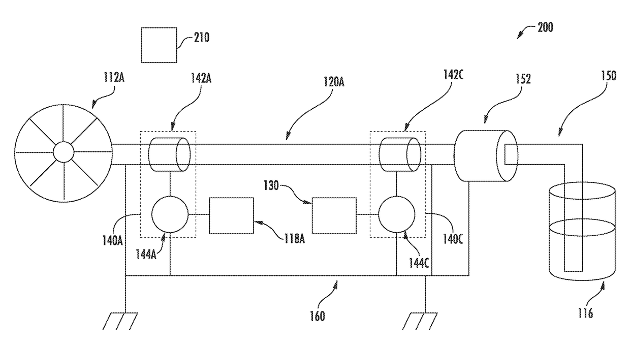
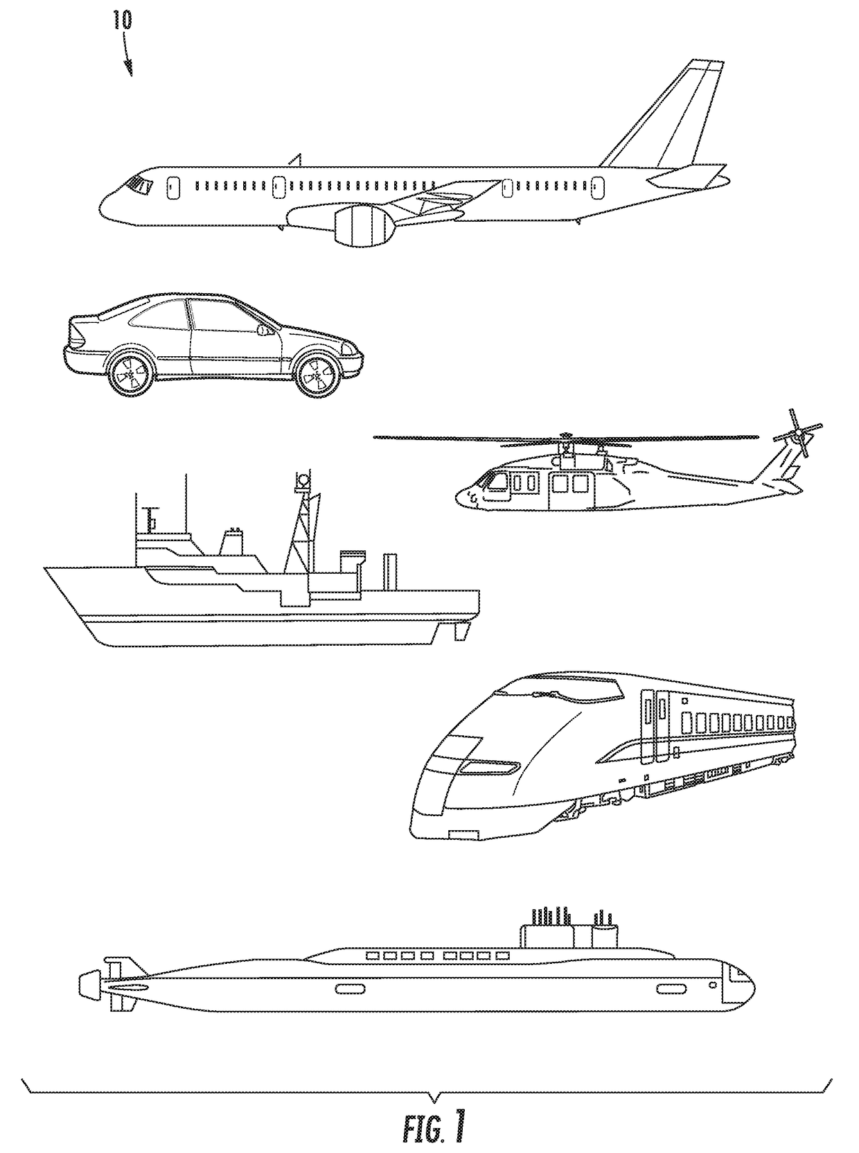
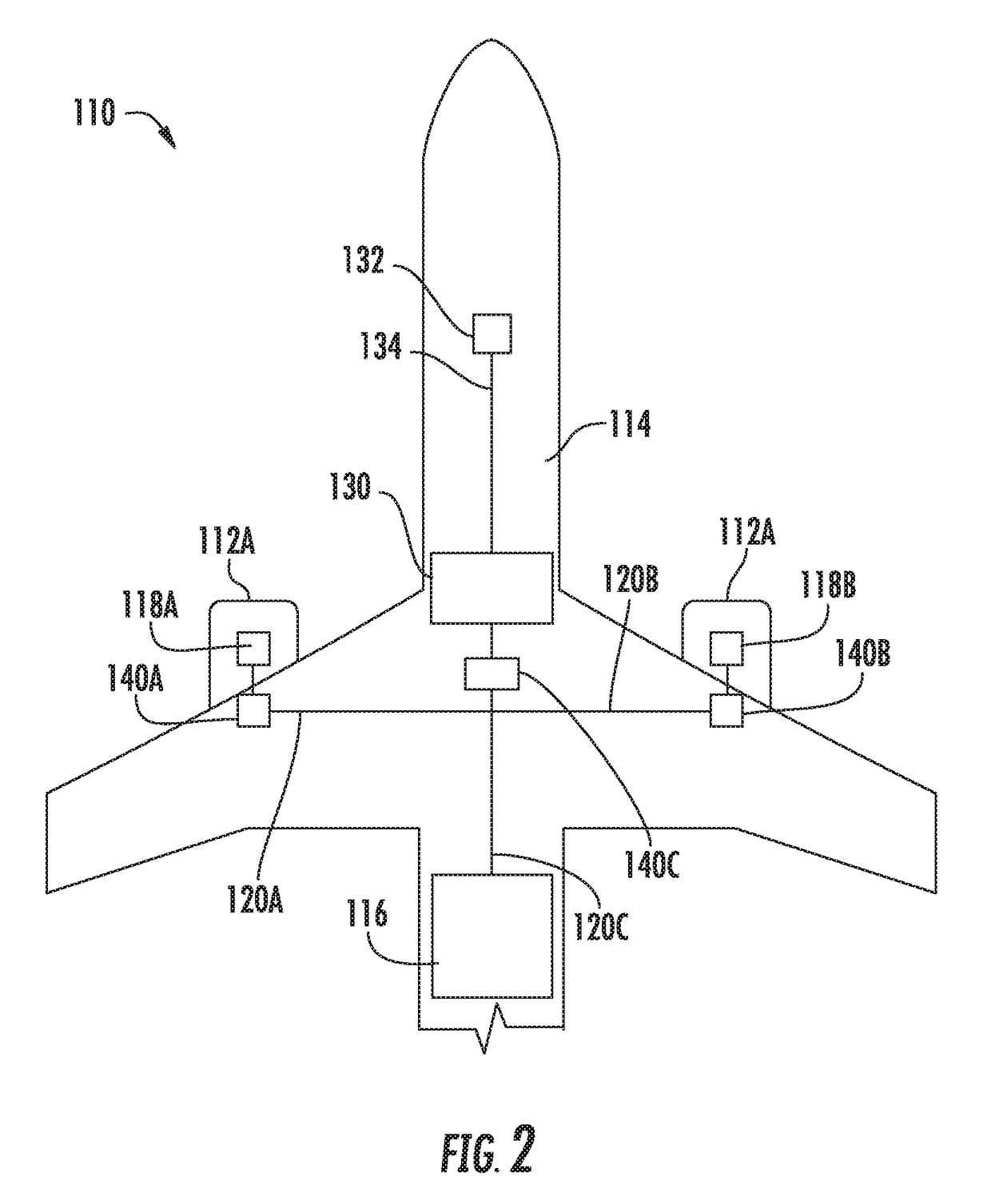
[0024]Example aspects of the present disclosure are directed to systems and methods of communicating signals over a fluid lines, such as fuel and hydraulic lines, in a vehicle, such as an aircraft, helicopter, automob...


PUM


Abstract

Systems and methods for communicating a signal over a hydraulic line in a vehicle are provided. In one embodiment, a system can include a hydraulic line. The hydraulic line can include at least one communication medium for propagating a communication signal. The system can also include at least one signal communication device configured to receive the communication signal communicated over the hydraulic line. The system can also include at least one vehicle component in communication with the at least one signal communication device.

Description

CROSS-REFERENCE TO RELATED APPLICATIONS[0001]The present application is a Continuation in Part of U.S. patent application Ser. No. 15 / 186,766 filed on Jun. 20, 2016, entitled “Communication of Signals Over Fuel Lines in a Vehicle”. application Ser. No. 15 / 186,766 is incorporated by reference herein in its entirety for all purposes.FIELD OF THE INVENTION[0002]The present subject matter relates generally to communicating signals over fluid lines in a vehicle, and more particularly, to communication of signals over fuel and hydraulic lines in a vehicle.BACKGROUND OF THE INVENTION[0003]Control of a vehicle, and in particular, a jet engine, ailerons, flaps, landing gear, and brakes on an aircraft, has evolved to use automated digital controls (e.g., a Full Authority Digital Engine Control (FADEC) on an aircraft). For example, a controller (e.g., an Electronic Engine Controller (EEC) or Electronic Control Unit (ECU) of a FADEC) can control fuel flow, engine geometries, and other parameter...

Claims


Application Information

Patent Timeline
IPC IPC(8): H04B3/52H04B13/02H04B11/00H04L29/08H04B3/54
CPCH04B3/52H04B3/54H04B13/02H04B11/00H04L67/12B60K15/00B64C13/36B64C13/40B64C13/503B64C25/22B64D31/14B64D37/00B64D37/005G08C23/00Y02T50/40
Inventor BOBREK, PAVLOGARDNER, ERIC RANKIN
Owner GE AVIATION SYST LLC
Why Eureka
Try Eureka