Inner rear-view mirror system for automobile with cameras

a rearview mirror and camera technology, applied in the field of vehicle parts, can solve the problems of inflexible installation structure, easy shooting blind angles in the rearview imaging device, car accidents,

Inactive Publication Date: 2018-01-04
PAN LEI
View PDF0 Cites 11 Cited by
  • Summary
  • Abstract
  • Description
  • Claims
  • Application Information

AI Technical Summary

Benefits of technology

[0033]With regard to the vehicle interior rearview mirror system with built-in cameras provided the present application, it can be known by analyzing the abovementioned structures: the license plate frame single-axis rotatable shooting device has a rotary telescopic structure and function, and can drive the first camera to adjust a shooting position (achieved by the rotation angle) and a shooting angle for the scenes behind the vehicle, which enables clear shooting of the scenes at two sides of the vehicle (the two sides of the vehicle body) and in the vicinity of the tires as obtained by the reversing camera; the vehicle roof triangular connection rod rotatable shooting device mainly has a structure of four second cameras, and can drive the four second cameras to perform front-back translation or left-right translation (achieving reciprocating movement), so as to achieve the object of telescopic movement, in this way, it can help the four second cameras shoot the scenes more clearly in front of the vehicle, behind the vehicle, on the left side of the vehicle and on the right side of the vehicle, respectively; in addition, the vehicle roof single-axis rotatable shooting device arranged on the top of the vehicle can drive the third camera to rotate and move along the circular path, with the length of the rotary handle as a radius, thereby achieving the object of rotational and movable shooting, and further, as the circular path of the rotary handle covers the front side, the rear side, the left side and the right side of the vehicle, each of the scenes in front of the vehicle, behind the vehicle, on the left side of the vehicle and on the right side of the vehicle can be clearly shot by the third camera. Furthermore, the first camera, the second cameras and the third camera are each in communication with the display on the center console. Therefore, panoramic shots of the rear bottom of the vehicle and some of the areas surrounding the vehicle, namely in front of the vehicle, behind the vehicle, on the left side of the vehicle and on the right side of the vehicle, can be accomplished by a combination of the first camera and the second cameras or a combination of the first camera and the third camera, and then transmitted to the display, such that the driver can obtain the panoramic shots displaying situation around the vehicle.
[0034]In addition, it should be noted that the abovementioned three device structures can be adapted to different vehicles for use. The vehicle interior rearview mirror system with cameras provided in the embodiments of the present application may have various installation modes and installation structures, which avoids the installation mode of the traditional rearview imaging devices that are generally installed below the taillight, and also overcomes the technical defects that the shooting visual angle is constrained and the images shot have blind angles.

Problems solved by technology

However, the above described prior art also has technical defects and problems in the following several aspects: 1. For the device (i.e., rearview imaging device) having the function of displaying vehicle reversing images in the prior art, since the reversing camera is fixedly installed at the rear of the vehicle (i.e. generally right behind the vehicle) and a rotation angle of the reversing camera is also fixed, shooting blind angles easily occur in the rearview imaging device in the prior art.
Moreover, the images with shooting blind angles often lead to misjudgment of the driver, thereby causing occurrence of car accidents.
In the specific structure, the installation mode and the installation structure of the traditional rearview imaging device are not flexible enough.
As the traditional rearview imaging device is generally installed below a taillight, such that the reversing camera can hardly shoot the scenes at two sides of the vehicle (two sides of the vehicle body) and in the vicinity of the rear tires.
The traditional reversing camera can only shoot some areas of the vehicle, rather than provide a panoramic view of the situation around the vehicle.
In conclusion, how to overcome the above technical defects in the prior art is a problem to be solved urgently by a person skilled in the art.

Method used


Image

  • Inner rear-view mirror system for automobile with cameras
  • Inner rear-view mirror system for automobile with cameras
  • Inner rear-view mirror system for automobile with cameras

Examples


embodiment 1

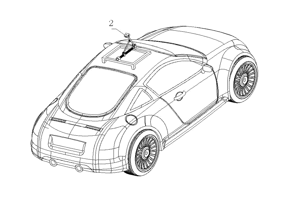
[0061]As shown in FIG. 1, a vehicle interior rearview mirror system with cameras provided in the present embodiment includes a license plate frame single-axis rotatable shooting device 1 provided on a license plate frame at the rear of a vehicle, and a vehicle roof triangular connection rod rotatable shooting device 2 provided on the top of the vehicle or a vehicle roof single-axis rotatable shooting device 3 provided on the top of the vehicle. Abovementioned devices are configured for driving the cameras to protrude out from the license plate frame or a roof rack to a position at a certain distance from the vehicle for shooting.

[0062]Specifically, as shown in FIG. 1, the license plate frame single-axis rotatable shooting device 1 includes a first camera 10. The license plate frame single-axis rotatable shooting device is configured for rotating about a border of the license plate frame 4 with the border as a rotation shaft, after the vehicle starts to reverse, so as to drive the fi...

embodiment 2

[0073]As to the basic structure provided in embodiment 1, comprised in the license plate frame single-axis rotatable shooting device provided in Embodiment 2, no further description is made herein.

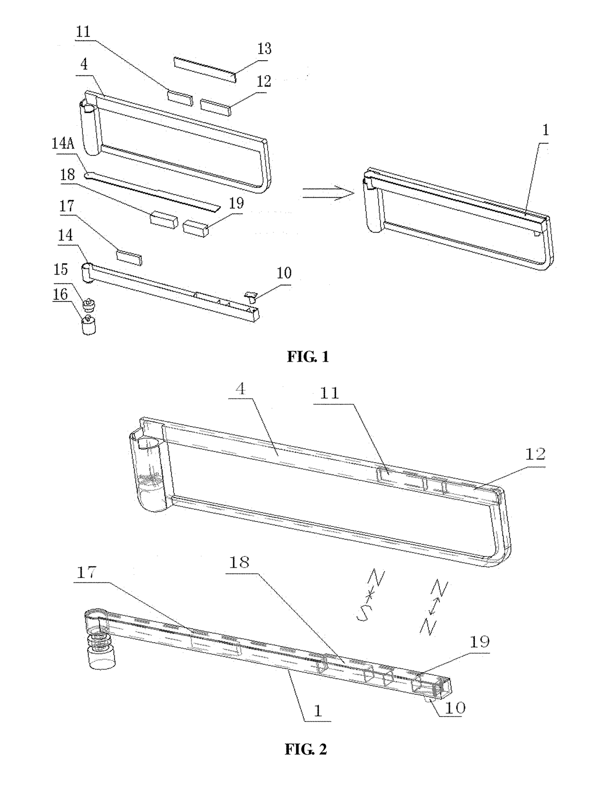
[0074]Referring to the specific schematic structural diagram of a license plate frame single-axis rotatable shooting device, as shown in FIG. 1 (which is specifically a schematic diagram for illustrating an assembly of the license plate frame single-axis rotatable shooting device from an exploded structure to an assembled structure), the license plate frame single-axis rotatable shooting device 1 further includes a first natural magnet 11, an electronic magnet 12 and a side cover plate 13 that are fixedly connected to the top border of the license plate frame 4. The side cover plate 13 is configured for encapsulating both the first natural magnet 11 and the electronic magnet 12 in the top border of the license plate frame 4.

[0075]The license plate frame single-axis rotatable shooting devic...

embodiment 3

[0078]As to the basic structure provided in Embodiment 1, comprised in the license plate frame single-axis rotatable shooting device provided in Embodiment 3, no further description is made herein.

[0079]As shown in FIG. 7, the license plate frame single-axis rotatable shooting device 1 further includes a first natural magnet 11, an electronic magnet 12 and a side cover plate 13 that are fixedly connected to the bottom border of the license plate frame 4. The side cover plate 13 is configured for encapsulating both the first natural magnet 11 and the electronic magnet 12 in the bottom border of the license plate frame.

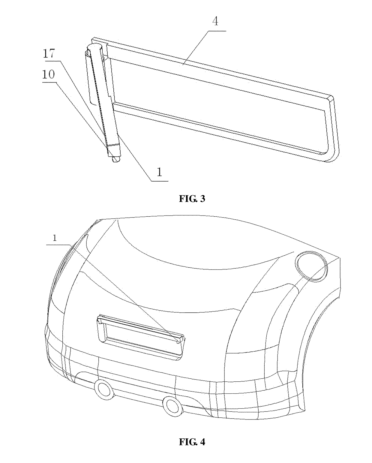
[0080]The license plate frame single-axis rotatable shooting device 1 further includes a rotary handle 14 which rotates in a plane where the bottom border of the license plate frame is located, and the rotary handle 14 rotates about the left border of the license plate frame 4. One end of the rotary handle 14 is rotationally connected with the bottom border of the licen...


PUM


Abstract

Disclosed is an inner rear-view mirror system for an automobile with cameras, which comprises a rotatable single-axle shooting device (1) of a license plate frame and a rotatable shooting device (2) with a triangular connecting rod on the top. The rotatable single-axle shooting device (1) of the license plate frame comprises a first camera (10). The rotatable single-axle shooting device (1) of the license plate frame is used for rotating about an edge of the license plate frame (4) as a rotation axis, so that the first camera (10) is driven to turn and protrude out of the spatial position of the license plate frame (4). The rotatable shooting device (2) with a triangular connecting rod on the top comprises four second cameras (20). The rotatable shooting device (2) with a triangular connecting rod on the top is used for driving the four second cameras (20) to horizontally move simultaneously along the front and back direction or the left and right direction of the vehicle. A rotatable single-axle shooting device (3) on the top comprises a third camera (30) and a rotary handle (31). The rotatable single-axle shooting device (3) of the roof is used for driving the third camera (30) to move along a circular path with the length of the rotary handle (31) as the radius. The above-mentioned inner rear-view mirror system for an automobile with cameras solves the technical problems, such as the blind angle present during shooting with a traditional inner rear-view mirror system for an automobile with cameras.

Description

TECHNICAL FIELD[0001]The present application relates to the field of vehicle parts, and particularly to a vehicle interior rearview mirror system with cameras.BACKGROUND ART[0002]In the prior art, many vehicles are installed with a device having a function of displaying vehicle reversing images. Such device generally has the following configurations: a reversing camera is usually installed at the rear of the vehicle, and a vehicle interior rearview mirror with a display hidden therein or other displays such as a DVD integrated machine are installed at the position of the center console in front of a driver (so that when reversing, the driver can clearly see the scene behind the vehicle directly through the display to know relevant conditions and environment during reversing, without looking back).[0003]In general, when it is shifted to a reverse gear by a driver, a signal of a reversing lamp is transmitted to the reversing camera and the display, and then the reversing camera and th...

Claims


Application Information

Patent Timeline
Patent Type & Authority Applications(United States)
IPC IPC(8): B60R11/04H04N7/18B60R1/00H04N5/225
CPCB60R11/04B60R1/00H04N7/181H04N5/2251B60R2300/301B60R2300/105B60R2300/8026B60R13/105B60R2011/004B60R2011/0082B60R2011/0084B60R2011/0085B60R2011/0092H04N23/51H04N23/50
Inventor PAN, LEI
Owner PAN LEI
Why Eureka
Try Eureka