
Apparatus and method for controlling a vehicle system

a vehicle system and apparatus technology, applied in the direction of vehicle cleaning, instruments, static indicating devices, etc., can solve the problems of unsatisfactory operation, electronic control units require calibration, and may be susceptible to varying usage patterns, so as to increase the activation threshold in dependence on the second request signal, and reduce the activation threshold in dependence

Inactive Publication Date: 2018-01-04
JAGUAR LAND ROVER LTD
View PDF1 Cites 5 Cited by
  • Summary
  • Abstract
  • Description
  • Claims
  • Application Information

AI Technical Summary

Benefits of technology

The present invention provides an apparatus for controlling operation of a vehicle system, which includes a processor for automatically controlling the vehicle system. The processor receives a measurement signal from a sensor associated with the vehicle system and outputs a control signal based on the measurement signal. The processor can detect user override of the automated operation of the vehicle system and re-calibrate the control function accordingly. This allows for user preferences to be incorporated into the control function. The control function can be a activation threshold or a deactivation threshold, and the processor can detect user operation of the vehicle system through a control interface or a touch sensor. The invention provides a control interface for direct control of the vehicle system by the user and enables automated control of the windshield wiper based on user operation of the control interface.

Problems solved by technology

The calibration of the rain sensor requires investment of engineering resources and may still provide unsatisfactory operation in certain scenarios.
This problem can be compounded by varying usage of the windshield wipers by different users.
Again, the electronic control unit requires calibration and may be susceptible to varying usage patterns by different users in certain operating conditions.

Method used


Image

  • Apparatus and method for controlling a vehicle system
  • Apparatus and method for controlling a vehicle system
  • Apparatus and method for controlling a vehicle system

Examples


Embodiment Construction

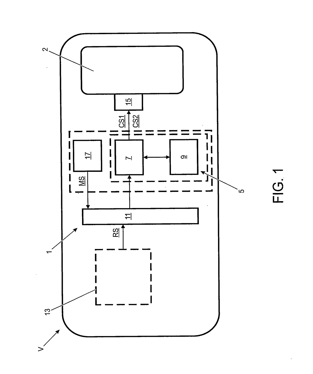
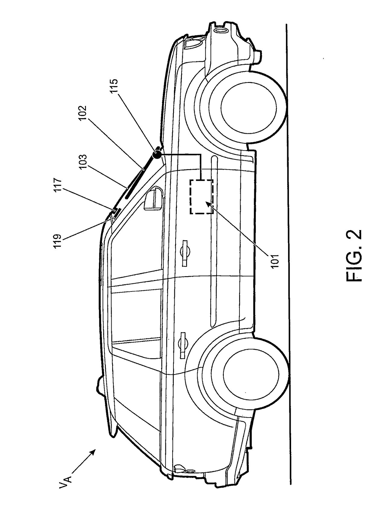
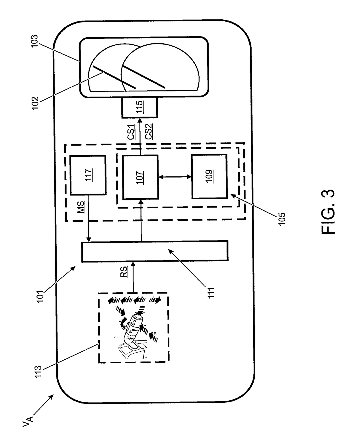
[0067]FIG. 1 shows an apparatus 1 for controlling operation of a vehicle system in accordance with an embodiment of the present invention. The apparatus 1 is installed in an automotive vehicle V to control operation of a vehicle system 2. As shown in FIG. 1, the apparatus 1 comprises a central processing unit 5. The central processing unit 5 comprises a processor 7 and system memory 9. The processor 7 is configured to execute a set of software instructions held in the system memory 9. The central processing unit 5 is connected to a communication bus 11, such as the vehicle CAN bus or FlexRay protocol, for communicating with one or more vehicle systems as described herein.

[0068]The central processing unit 5 is connected to a control interface 13 for controlling operation of the vehicle system 2. The control interface 13 is arranged to provide at least a first output. When the control interface 13 provides a first output, a corresponding request signal RS is published to the communica...


PUM


Abstract

The present disclosure relates to apparatus for controlling operation of a vehicle system. The apparatus includes a processor operable in an automatic mode to output a control signal to automate operation of the vehicle system. The processor is configured to receive a measurement signal from a sensor associated with the vehicle system. The processor outputs the control signal in dependence on a comparison of the measurement signal to a control function. A user override of the automated operation of the vehicle system is detected and the processor re-calibrates the control function in dependence on the detected user override. The present disclosure also relates to a vehicle and to a method of controlling operation of a vehicle system.

Description

TECHNICAL FIELD[0001]The present disclosure relates to an apparatus and method for controlling a vehicle system. In particular, but not exclusively, embodiments of the invention relate to an apparatus and method for automatically controlling components of a vehicle. Components of a vehicle which can be automatically controlled include, but are not limited to, windshield wipers, headlights and sound generating devices. Aspects of the present invention relate to an apparatus, to a vehicle and to a method of controlling a vehicle system.BACKGROUND[0002]It is known to provide automated windshield wipers on road vehicles, such as automotive vehicles. A rain sensor is typically disposed behind the windshield to determine when a wipe action is required. The rain sensor detects moisture due to rain and outputs a measurement signal to an electronic control unit configured to control an operating speed and / or frequency of wiper motor. The rain sensor can, for example, comprise an optical sens...

Claims


Application Information

Patent Timeline
Patent Type & Authority Applications(United States)
IPC IPC(8): B60S1/08
CPCB60S1/0822B60S1/0818B60Q1/1423B60R16/0231B60R16/0315B60S1/08B60Q1/1476G09G3/3233B60S1/0803B60S1/0807
Inventor STEWARD, DAREN
Owner JAGUAR LAND ROVER LTD
Learn More