Brake beam fatigue test stand
a technology for testing stands and brake beams, which is applied in the field of rail transit, can solve the problems of low test efficiency, low strength of the gantry of the test stand, and the inability of the test stand to adapt to brake beams of different types
- Summary
- Abstract
- Description
- Claims
- Application Information
AI Technical Summary
Benefits of technology
Problems solved by technology
Method used
Image

Examples
Embodiment Construction
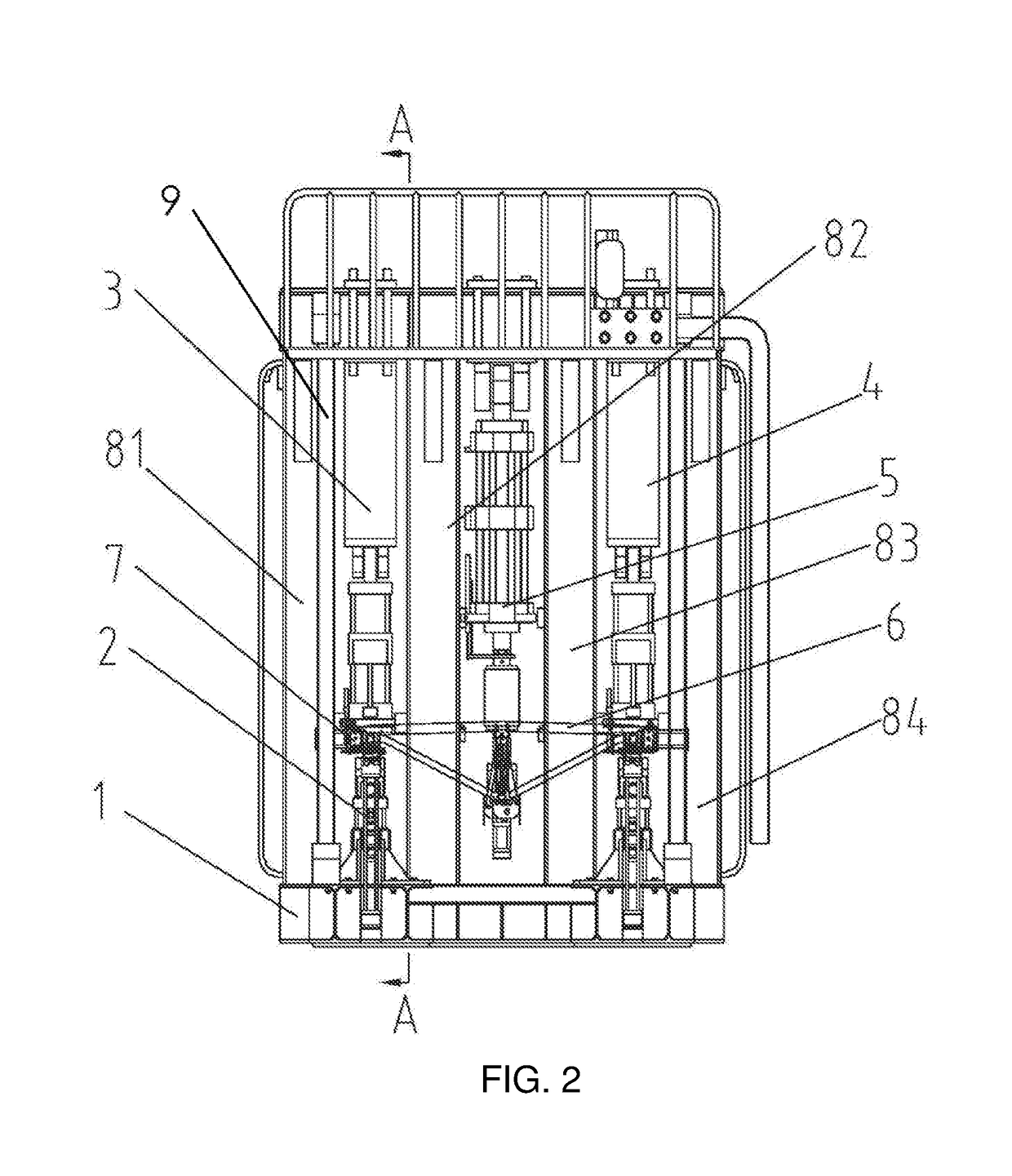
[0048]The present application will be described in detail below by exemplary embodiments. However, it should be understood that, unless otherwise stated, elements, structures and features in one embodiment can be beneficially combined into other embodiments. Meanwhile, in the description of the present application, it should be noted that orientations or positional relationships indicated in the brake beam fatigue test stand by terms such as “upper”, “lower”, “front”, “rear”, “top”, “bottom” are the positional relationships illustrated on the basis of FIG. 2. Those terms are used merely for ease of describing the present application and simplifying the description, not for indicating or implying that the involved device or element must have a specific orientation or be constructed and operated in the specific orientation. Therefore, they shall not be considered as limitations to the present application. In the drawings provided by the present application, view directions of FIGS. 3 ...
PUM
| Property | Measurement | Unit |
|---|---|---|
| diameter | aaaaa | aaaaa |
| diameter | aaaaa | aaaaa |
| fatigue strength | aaaaa | aaaaa |
Abstract
Description
Claims
Application Information
 - R&D Engineer
- R&D Manager
- IP Professional
- Industry Leading Data Capabilities
- Powerful AI technology
- Patent DNA Extraction
Browse by: Latest US Patents, China's latest patents, Technical Efficacy Thesaurus, Application Domain, Technology Topic.
© 2024 PatSnap. All rights reserved.Legal|Privacy policy|Modern Slavery Act Transparency Statement|Sitemap