Fixing device and image forming apparatus
a fixing device and image forming technology, applied in the direction of electrographic process apparatus, instruments, optics, etc., can solve the problems of fixation failure, increase of load on the fixing belt, and projection and depression of the recording medium, so as to reduce the preheating electricity and shorten the activation time. , the effect of small heat capacity
- Summary
- Abstract
- Description
- Claims
- Application Information
AI Technical Summary
Benefits of technology
Problems solved by technology
Method used
Image
Examples
first embodiment
Fixing Device 100A . . . Changing Belt Discharge Angle
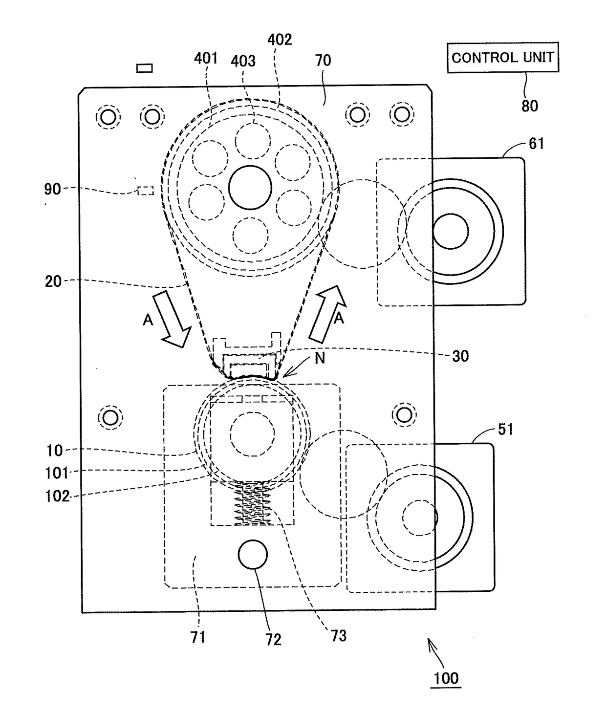
[0080]Referring to FIG. 8 to FIG. 10, the configuration of a fixing device 100A in a first embodiment will be described. FIG. 8 is a partial enlarged view showing the configuration of fixing device 100A, FIG. 9 is a side view showing the configuration of the fixing device in a “mode I” state, and FIG. 10 is a side view showing the configuration of the fixing device in a “mode II” state.
[0081]The basics such as fixing pad 30, heating roller 40, and pressing roller 10 are as described above, except that pressing roller 10 and fixing pad 30 are supported by a side chassis 113. Pressing roller 10, which is not shown in detail in the figure, presses fixing pad 30 and has a retraction mechanism that is retracted from the position opposed to fixing pad 30 when not used. Heating roller 40 is supported by a side chassis 111.
[0082]Side chassis 111 is pivotably supported on a base chassis 112 using a rotational shaft 114, and side chassis 1...
second embodiment
Fixing Device 200 . . . Changing Belt Discharge Angle
[0093]Referring to FIG. 11 and FIG. 12, a fixing device 200 in a second embodiment will be described. The principal member configuration and structure is the same as in fixing device 100 and fixing device 100A above, and an overlapping description will not be repeated. FIG. 11 is a diagram showing the control state in “mode I” in fixing device 200, and FIG. 12 is a diagram showing the control state in “mode II” in fixing device 200.
[0094]Referring to FIG. 11, this fixing device 200 is configured such that the angle of fixing belt 20 fed from fixing pad 30 is changed by a belt pushing member 212. Belt pushing member 212 is a cam fixed to a shaft 215, arranged on the inner surface of fixing belt 20, and rotatably fixed to side chassis 70 by shaft 215 in parallel with fixing pad 30.
[0095]Shaft 72 has a switch handle 211 fixed thereto. This switch handle 211 is swung upward or downward to turn belt pushing member 212 to push fixing be...
third embodiment
Fixing Device 300 . . . Changing Belt Discharge Angle
[0099]Referring to FIG. 13, a fixing device 300 in a third embodiment will be described. The principal member configuration and structure is the same as in the above-noted fixing device 100, 100A, 200, and an overlapping description will not be repeated. FIG. 13 is a diagram showing the control state in “mode I” in fixing device 300.
[0100]Referring to FIG. 13, this fixing device 300 is configured such that the angle of fixing belt 20 fed from fixing pad 30 is changed by an idle roller 304. Idle roller 304 is supported by a bearing 301 on side chassis 70 so as to be movable horizontally. In the inside of bearing 301, a sliding member 305 with a guide roller 303 is disposed.
[0101]Sliding member 305 is biased toward idle roller 304 by a spring member 302. Idle roller 304 is turned about its axis to move in the right-left direction in the figure, and sliding member 305 also moves in the right-left direction along with this movement. A...
PUM
 Abstract
Description
Claims
Application Information
 - R&D
- Intellectual Property
- Life Sciences
- Materials
- Tech Scout
- Unparalleled Data Quality
- Higher Quality Content
- 60% Fewer Hallucinations
Browse by: Latest US Patents, China's latest patents, Technical Efficacy Thesaurus, Application Domain, Technology Topic, Popular Technical Reports.
© 2025 PatSnap. All rights reserved.Legal|Privacy policy|Modern Slavery Act Transparency Statement|Sitemap|About US| Contact US: help@patsnap.com


