Drip leg for air handling system

a technology of air handling system and drip leg, which is applied in the field of pneumatic air handling system sediment trap and pneumatic apparatus, can solve the problems of frequent maintenance or replacement of filter screen, poor quality of incoming air, and significant corrosion of supply piping

Inactive Publication Date: 2018-02-01
ZAYTRAN
View PDF2 Cites 1 Cited by
  • Summary
  • Abstract
  • Description
  • Claims
  • Application Information

AI Technical Summary

Benefits of technology

[0011]According to yet another exemplary aspect, an air preparation system is provided, wherein the air preparation system comprises the above-described sediment trap, in addition to one or more supplemental air preparation apparatuses. As such, the outlet conduit of the sediment trap is fluidly coupled to the one or more supplemental air preparation apparatuses in an advantageous manner. The one or more supplemental air preparation apparatuses, for example, can compri

Problems solved by technology

In a typical factory environment, the quality of incoming air can be poor, and corrosion within the supply piping can be significant.
Thus, depending on the condition of the air prior to compression, as well as

Method used


Image

  • Drip leg for air handling system
  • Drip leg for air handling system
  • Drip leg for air handling system

Examples


Embodiment Construction

[0016]The present disclosure will be described with reference to the drawings wherein like reference numerals are used to refer to like elements throughout. It should be understood that the description of these aspects are merely illustrative and that they should not be taken in a limiting sense. In the following description, for purposes of explanation, numerous specific details are set forth in order to provide a thorough understanding of the present disclosure. It will be evident to one skilled in the art, however, that the present disclosure may be practiced without these specific details. In other instances, well-known structures and devices are shown in block diagram form in order to facilitate description of the present disclosure.

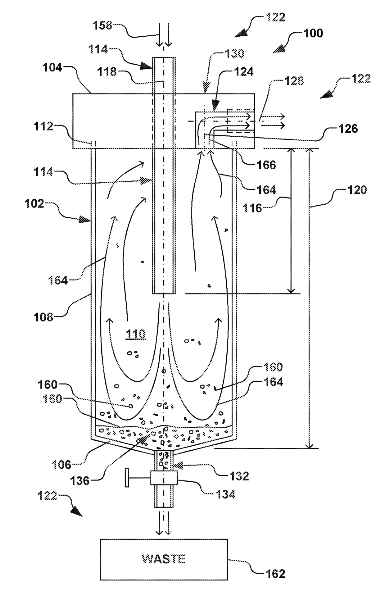
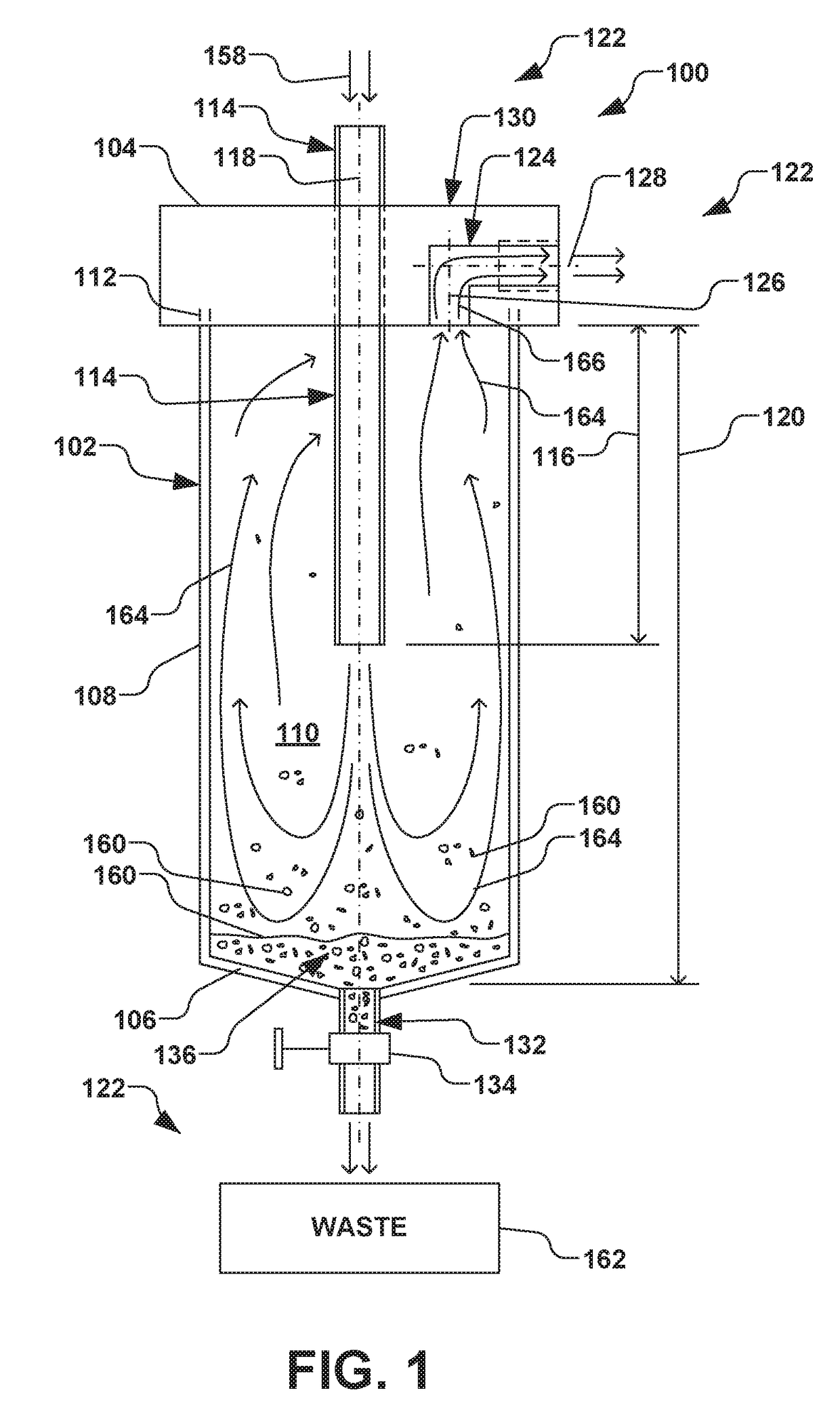
[0017]Referring initially to FIG. 1, a sediment trap 100 (also called a drip leg) is provided, wherein the sediment trap is configured to entrain substantial contamination associated with conventional compressed air, such as raw compressed air (e.g....


PUM

PropertyMeasurementUnit
Angleaaaaaaaaaa
Lengthaaaaaaaaaa
Pressureaaaaaaaaaa

Abstract

A sediment trap and air preparation apparatus including the sediment is provided. The sediment trap has a chamber with top and bottom caps, separated by a sidewall that generally encloses an interior region of the chamber. An inlet conduit is coupled to the top cap, where the inlet conduit extends into the interior region of the chamber by at least one-quarter of a length of the chamber. The inlet conduit fluidly couples the interior region of the chamber to an exterior region. An outlet conduit is coupled to the top cap and has first and second outlet axes offset by approximately ninety degrees. The outlet conduit fluidly couples the interior and exterior regions of the chamber. A clean-out conduit is coupled to the bottom cap and further selectively fluidly couples the interior and exterior regions of the chamber. One or more supplemental air preparation apparatuses, are further fluidly coupled to the outlet conduit.

Description

FIELD[0001]The present invention relates generally to pneumatic systems, and more particularly, to a sediment trap and pneumatic apparatus for air handling systems.BACKGROUND[0002]Air handling systems, also called pneumatic systems, are commonplace in various industries, such as the automotive industry. In a typical air handling system, atmospheric air is compressed and provided to various locations throughout a factory floor via supply piping that is often comprised of iron. The compressed air is subsequently filtered, pressure-regulated, oiled, or otherwise conditioned prior to being supplied to pneumatic tooling or other apparatuses requiring pressurized air.[0003]Conventionally, filtering of the compressed air is performed using various filter elements, whereby multiple screens filter various-sized contaminants from the compressed air prior to the compressed air reaching the pneumatic tooling or apparatuses. In a typical factory environment, the quality of incoming air can be po...

Claims


Application Information

Patent Timeline
IPC IPC(8): B01D45/06B01D50/00
CPCB01D50/002B01D45/06B01D50/20
Inventor ZAJAC, JR., THEODORE STANLEY
Owner ZAYTRAN
Why Eureka
Try Eureka