Image capturing apparatus and manufacturing method thereof

a technology of image capturing apparatus and manufacturing method, which is applied in the field of optoelectronic apparatus and a manufacturing method thereof, can solve the problems of negative impact on the image capturing quality of the image capturing apparatus, and achieve the effect of excellent image capturing quality

Active Publication Date: 2018-02-08
GINGY TECH
View PDF2 Cites 5 Cited by
  • Summary
  • Abstract
  • Description
  • Claims
  • Application Information

AI Technical Summary

Benefits of technology

[0006]The invention provides an image capturing apparatus that exhibits excellent image capturing quality.

Problems solved by technology

Since the light source in the optical-type biometric identification apparatus is disposed next to the sensor, large-angle beams emitted by the light source may directly irradiate to the sensor and cause interference.
If a light shielding element is disposed between the light source and the sensor to reduce interference, transmission of the beam may be affected and the finger may not be uniformly irradiated by the beam, which causes negative impact on image capturing quality of the image capturing apparatus.

Method used


Image

  • Image capturing apparatus and manufacturing method thereof
  • Image capturing apparatus and manufacturing method thereof
  • Image capturing apparatus and manufacturing method thereof

Examples


first embodiment

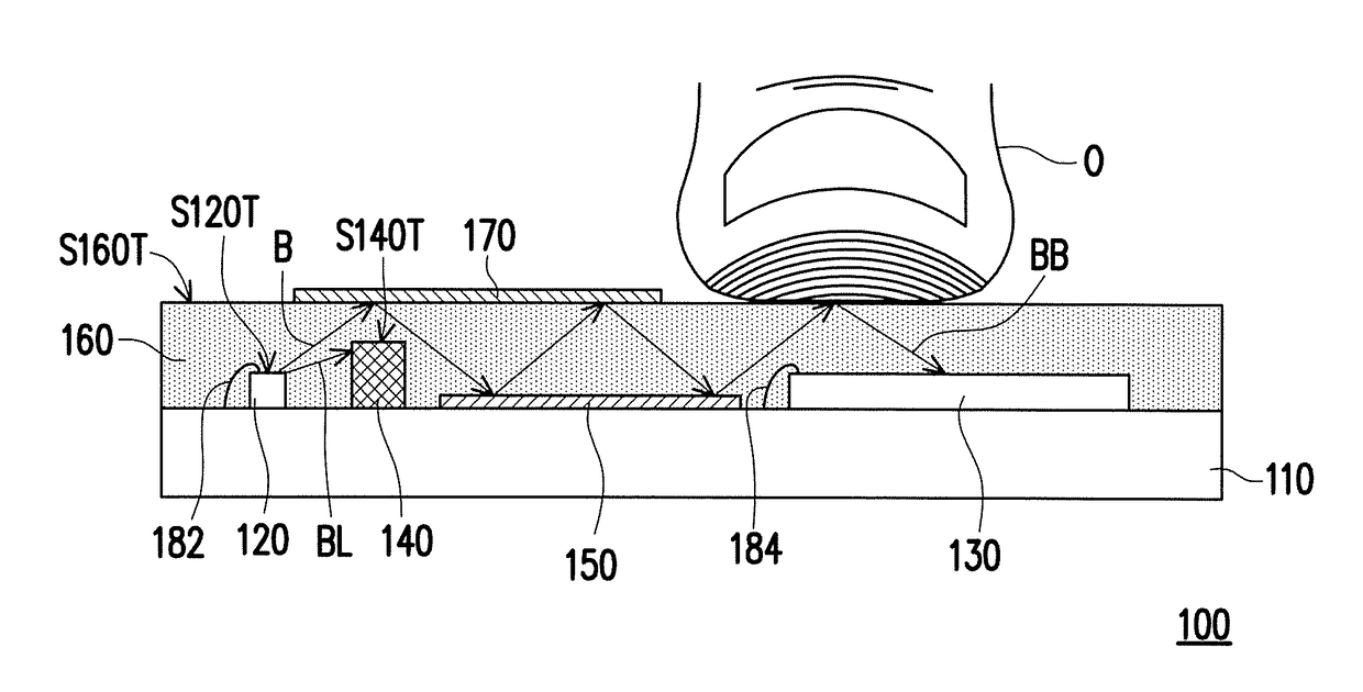
[0026]FIG. 1 is a cross-sectional schematic diagram illustrating one aspect of an image capturing apparatus according to the invention. Referring to FIG. 1, an image capturing apparatus 100 is adapted to capture a biometric feature of an object O. In the exemplary embodiment, the object O is, for example, a finger, and the biometric feature is, for example, a fingerprint or a vein, but the invention is not limited hereto. For example, in another embodiment, the object O may also be a palm, and the biometric feature may be a palm print.

[0027]The image capturing apparatus 100 includes a substrate 110, a light source 120, a sensor 130, a light shielding element 140, a first reflective element 150, a transparent colloid curing layer 160, and a second reflective element 170.

[0028]The substrate 110 is used as a carrier board of the foregoing components, and the substrate 110 may include a circuit. For example, the substrate 110 is a printed circuit board (PCB), a flexible printed circuit ...

second embodiment

[0058]FIG. 9 is a cross-sectional schematic diagram illustrating another aspect of the image capturing apparatus according to the Referring to FIG. 9, an image capturing apparatus 200A is similar to the image capturing apparatus 200 of FIG. 8, wherein the same components are represented by the same numerals and will not be repeatedly described below. The main differences between the image capturing apparatus 200A and the image capturing apparatus 200 of FIG. 8 are described below. In the image capturing apparatus 200A, the image capturing apparatus 200A further includes the wall structure 112 (also known as protective structure) and the transparent cover TC. Reference may be made to the relevant paragraphs above for relevant descriptions of the wall structure 112 and the transparent cover TC, which will not be repeated here.

[0059]In the framework of FIG. 9, the transparent cover TC protects the transparent colloid curing layer 160 and the second reflective element 170 located below...

third embodiment

[0089]FIG. 14 is a cross-sectional schematic diagram illustrating one aspect of an image capturing apparatus according to the invention. Referring to FIG. 14, an image capturing apparatus 300 is similar to the image capturing apparatus 100 of FIG. 1, wherein the same components are represented by the same numerals and will not be repeatedly described below. The main differences between the image capturing apparatus 300 and the image capturing apparatus 100 of FIG. 1 are described below. In the image capturing apparatus 300, the second reflective element 170 in FIG. 1 is omitted. In this case, a portion of the beam B transmitted to the top surface S160T of the transparent colloid curing layer 160 is transmitted to the first reflective element 150 through internal reflection. Specifically, when a thickness T160 of the transparent colloid curing layer 160 is within a range from 0.3 mm to 1.8 mm, a portion of the beam transmitted to the top surface S160T of the transparent colloid curin...


PUM


Abstract

An image capturing apparatus including a substrate, a light source, a sensor, a light shielding element, a first reflective element, and a transparent colloid curing layer is provided. The light source, the sensor, the light shielding element, the first reflective element, and the transparent colloid curing layer are disposed on the substrate. The sensor is located next to the light source. The light shielding element is located between the light source and the sensor. The first reflective element is located between the light shielding element and the sensor. The transparent colloid curing layer covers the light source, the sensor, the light shielding element, and the first reflective element. A manufacturing method of the image capturing apparatus is also provided.

Description

CROSS-REFERENCE TO RELATED APPLICATION[0001]This application is a continuation-in-part application of and claims the priority benefit of a prior application Ser. No. 15 / 588,700, filed on May 8, 2017, now pending, which claims the priority benefits of U.S. provisional application Ser. No. 62 / 371,230, filed on Aug. 5, 2016, U.S. provisional application Ser. No. 62 / 413,974, filed on Oct. 27, 2016, and China application serial no. 201720260844.9, filed on Mar. 17, 2017. This application is also a continuation-in-part application of and claims the priority benefit of a prior application Ser. No. 15 / 399,704, filed on Jan. 5, 2017, now pending, which claims the priority benefits of U.S. provisional application Ser. No. 62 / 371,230, filed on Aug. 5, 2016, U.S. provisional application Ser. No. 62 / 413,974, filed on Oct. 27, 2016, and Taiwan application serial no. 105135846, filed on Nov. 4, 2016. This application also claims the priority benefits of Taiwan application serial no. 106121692, fil...

Claims


Application Information

Patent Timeline
Patent Type & Authority Applications(United States)
IPC IPC(8): G06K9/46G06K9/00
CPCG06K9/46G06K9/00892G06K9/00013G06K9/00053G06V40/1329G06V40/1318G06V40/70
Inventor YOU, KUO-LIANGYANG, KUO-WENHUANG, CHENG-JYUNCHIU, YU-CHENGCHANG, HAO-HSIANGYU, CHIH-CHIANG
Owner GINGY TECH
Why Eureka
Try Eureka