Control device for actuator, actuator, valve driving device and control method for actuator

a technology of actuators and control devices, applied in the direction of electric motor control, mechanical equipment, transportation and packaging, etc., can solve problems such as performance degradation

Active Publication Date: 2018-02-08
MITSUBISHI ELECTRIC CORP
View PDF6 Cites 6 Cited by
  • Summary
  • Abstract
  • Description
  • Claims
  • Application Information

AI Technical Summary

Benefits of technology

[0008]According to the present invention, because the intra-sensor temperature detected by the temperature detecting element built in the position sensor is acquired, the inter...

Problems solved by technology

In a direct-current motor used as a driving source of an actuator, its performance degrad...

Method used


Image

  • Control device for actuator, actuator, valve driving device and control method for actuator
  • Control device for actuator, actuator, valve driving device and control method for actuator
  • Control device for actuator, actuator, valve driving device and control method for actuator

Examples


embodiment 1

[0016]A case of using an actuator according to the present invention as a wastegate (hereinafter referred to as WG) actuator that drives a WG valve of a turbocharger that is mounted in a vehicle will be explained as an example.

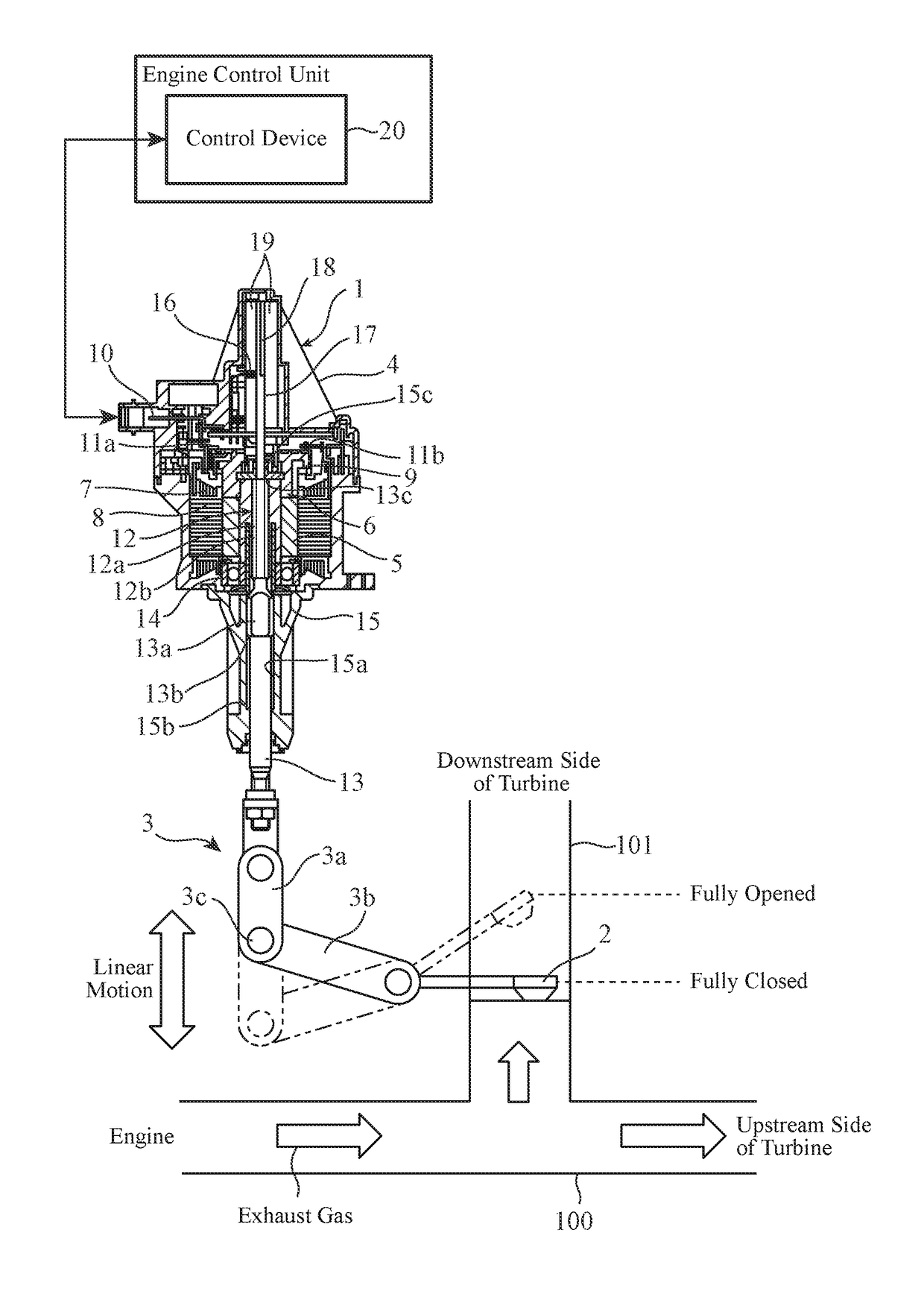
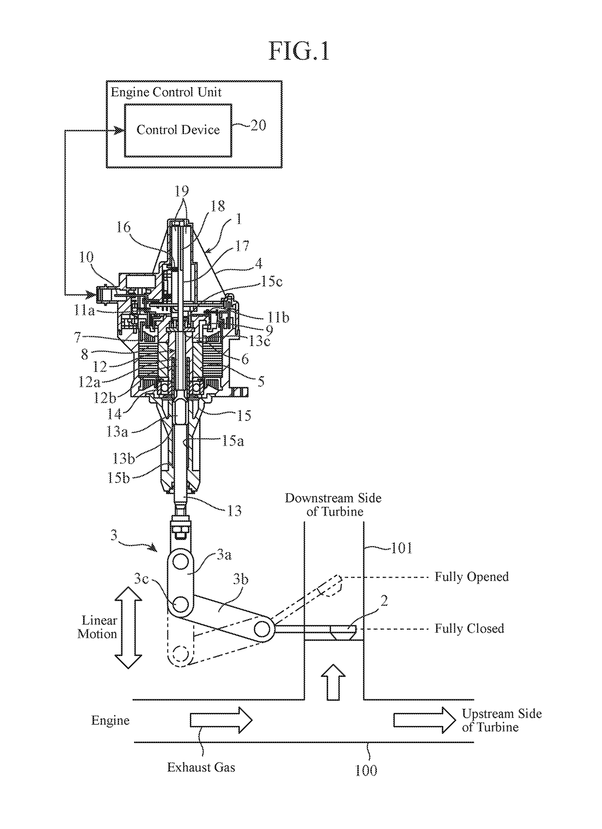
[0017]FIG. 1 is a cross-sectional view showing an example of the configuration of a WG actuator 1 according to Embodiment 1. The turbocharger is configured so as to rotate a turbine by using an exhaust gas from an engine, drive a compressor connected with this turbine on the same axis, compress intake air, and supply this compressed intake air to the engine. A WG valve 2 for bypassing the exhaust gas from an exhaust passage 100 to a bypass passage 101 is disposed on an upstream side of the exhaust passage 100 with respect to the turbine. The number of rotations of the turbine is controlled by opening or closing the WG valve 2 to adjust the inflow of the exhaust gas from the exhaust passage 100 to the bypass passage 101 by means of the WG actuator 1. In FIG. 1,...

embodiment 2

[0047]FIG. 6 is a block diagram showing an example of the configuration of a control device 20 for a WG actuator 1 according to Embodiment 2 of the present invention. In FIG. 6, the same components as those shown in FIG. 3 or like components are designated by the same reference numerals, and the explanation of the components will be omitted hereafter. Because the WG actuator 1 which is an object to be controlled by the control device 20 according to Embodiment 2 has the same configuration as that according to above-mentioned Embodiment 1, the WG actuator will be explained using FIGS. 1 and 2.

[0048]The control device 20 according to Embodiment 2 includes a coil temperature estimating unit 26 that estimates the temperature of the coil 7 of a direct-current motor 4. Hereafter, the temperature of the coil 7 of the direct-current motor 4 is referred to as the “coil temperature.” As a method of estimating the coil temperature, a well-known method, for example, a method of detecting the va...


PUM


Abstract

A position sensor mounted in an actuator includes a magnetic detecting element for detecting the position of a shaft, and a temperature detecting element for detecting intra-sensor temperature which is used for correction of the temperature characteristics of the magnetic detecting element, the magnetic detecting element and the temperature detecting element being built therein. A control device for the actuator acquires both the temperature-corrected position of the shaft and the intra-sensor temperature from the position sensor, and uses them for control of the actuator.

Description

TECHNICAL FIELD[0001]The present invention relates to a control device for an actuator that uses a direct-current motor as a driving source, an actuator, a valve driving device and a control method for an actuator.BACKGROUND ART[0002]In a direct-current motor used as a driving source of an actuator, its performance degrades when the temperature of coils thereof rises due to the passage of currents through the coils. For this reason, conventionally, an independent temperature sensor is disposed in the direct-current motor, to detect the temperature (for example, refer to Patent Literature 1), or the coil temperature is estimated on the basis of the currents passing through the coils and the time period during which the currents pass through the coils, to limit the current passing through the direct-current motor on the basis of the temperature, thereby preventing performance degradation.CITATION LISTPatent Literature[0003]Patent Literature 1: Japanese Unexamined Patent Application Pu...

Claims


Application Information

Patent Timeline
IPC IPC(8): H02P29/64H02P29/66H02K21/14B60L15/20H02K11/25
CPCH02P29/64B60L15/20H02K11/25H02K21/14H02P29/662B60L2240/16B60L2240/36B60L2240/425H02P29/60H02P7/02Y02T10/72F16H61/32
Inventor KAWAMURA, SATOSHIHATANO, KENTA
Owner MITSUBISHI ELECTRIC CORP
Why Eureka
Try Eureka