
Temperature control system of laser device in laser online gas analyzer

A technology for temperature control systems and gas analyzers, applied in temperature control, control/regulation systems, instruments, etc., can solve problems such as low stability, optical grating drift, and difficulty in completing temperature control, and achieve the effect of precise tuning

Active Publication Date: 2014-12-03
山西国惠华光科技有限公司
View PDF7 Cites 13 Cited by
  • Summary
  • Abstract
  • Description
  • Claims
  • Application Information

AI Technical Summary

Problems solved by technology

[0002] In the laser online gas analysis system, the laser is a very important device. In the current laser online gas analysis system, there are two technologies used: direct absorption spectroscopy and wavelength modulation spectroscopy (WMS). Compared with direct absorption Spectroscopy technology, wavelength modulation spectroscopy (WMS) is more widely used because it can increase the measurement sensitivity of the system by 100~1000 times; in the laser online gas analysis system using WMS, if you want to accurately measure the gas concentration , it is necessary to be able to change the wavelength of the laser linearly and with high resolution, while the wavelength of the laser and the optical grating in the probe are susceptible to drift due to temperature, which in turn affects the performance of the entire gas analysis system
[0003] In order to solve the above problems, a temperature controller is usually set in the laser to keep the internal temperature of the laser within a certain range, so as to achieve precise tuning of the output wavelength of the laser, and the common way to set the temperature controller in the laser is: A thermoelectric cooler (TEC) and a thermistor are integrated inside the laser. The thermoelectric cooler (TEC) is also called a semiconductor cooler. When a current flows through the TEC, the heat generated by the current will be transferred from one side of the TEC to the other. In this way, one end of the TEC absorbs heat and the other end releases heat, thereby realizing the heating and cooling functions of the TEC. When working, the thermistor detects the temperature inside the laser in real time, and controls the flow through the temperature control circuit. The size and direction of the current of the TEC makes the heat transfer from one side of the TEC to the other side, thereby controlling the internal die temperature of the laser and ensuring the normal operation of the laser; currently, the wavelength tuning range of the DFB laser only reaches 3~5nm, and the gas The absorption linewidth of the laser is generally on the order of 10pm. According to theoretical calculations, in order to achieve precise tuning of the laser wavelength, the temperature stability of the temperature control system must reach above 0.02°C; at present, most of the commonly used TEC temperature control circuits are built with discrete components. And the parameter values ​​are determined according to the experience of the designer, the control accuracy is low, and the discrete components are more susceptible to noise interference in the design, which not only makes the accuracy difficult to control, but also makes it difficult to complete the temperature control. The temperature control stability of the better temperature controllers in the domestic market can only reach 0.1°C, and the temperature controllers that can meet the demand in the foreign market are expensive, and some are even as high as tens of thousands of dollars. Therefore, there is an urgent need Seek a self-developed temperature control system for lasers in laser online gas analyzers with high-precision temperature control performance to achieve stable control output for laser wavelengths

Method used


Image

  • Temperature control system of laser device in laser online gas analyzer
  • Temperature control system of laser device in laser online gas analyzer

Examples


Embodiment Construction

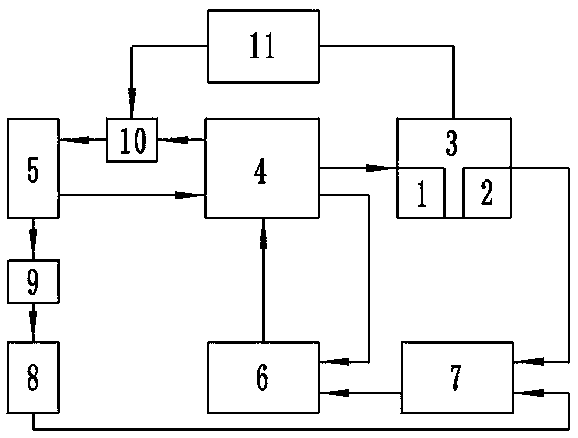
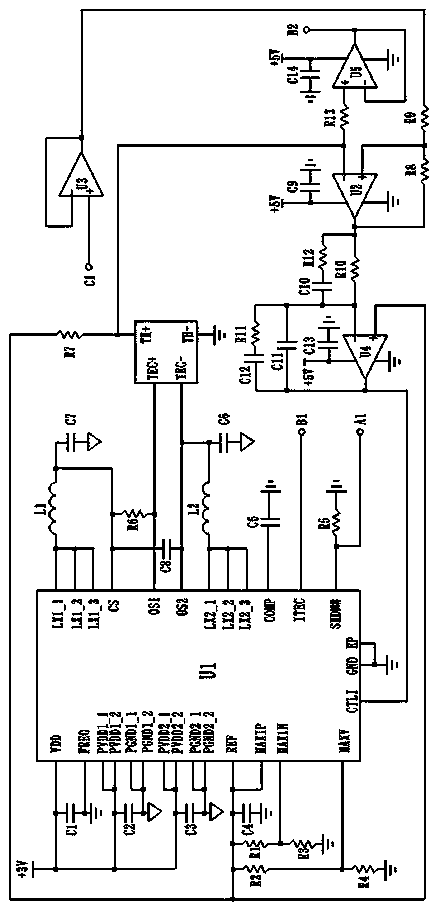
[0013] Such as figure 1 As shown, the temperature control system of the laser in the laser online gas analyzer includes: a laser body 3 with a thermoelectric cooler 1 and a thermistor 2 inside, and the temperature control system also includes: a thermoelectric cooler drive circuit 4, FPGA Chip 5, PID controller 6, subtractor 7, voltage follower 8, DAC converter 9, ADC converter 10, and temperature monitoring circuit 11. The thermoelectric cooler drive circuit 4 is connected to FPGA chip 5 and PID controller 6 respectively Connected to the laser body 3, the subtractor 7 is respectively connected to the PID controller 6, the voltage follower 8 and the laser body 3, the voltage follower 8 is connected to the FPGA chip 5 through the DAC converter 9, and the FPGA chip 5 It is also connected to the thermoelectric cooler driving circuit 4 and the temperature monitoring circuit 11 through the ADC converter 10, and the temperature monitoring circuit 11 is connected to the laser body 3.

...


PUM


Abstract

The invention discloses a temperature control system of a laser device in a laser online gas analyzer. The temperature control system of the laser device in the laser online gas analyzer has high temperature control precision. According to the technical scheme, the temperature control system comprises a laser device body, a thermoelectric refrigerating unit drive circuit, an FPGA chip, a PID controller, a subtracter, a voltage follower, a DAC, an ADC and a temperature monitor circuit. The thermoelectric refrigerating unit drive circuit is respectively connected with the FPGA chip, the PID controller and the laser device body, the subtracter is respectively connected with the PID controller, the voltage follower and the laser device body, the voltage follower is connected with the FPGA chip through the DAC, the FPGA chip is respectively connected with the thermoelectric refrigerating unit drive circuit and the temperature monitor circuit through the ADC, and the temperature monitor circuit is connected with the laser device body. The temperature control system is suitable for the field of the laser device.

Description

Technical field [0001] The invention relates to a temperature control system, in particular to a temperature control system of a laser in a laser online gas analyzer. Background technique [0002] In the laser online gas analysis system, the laser is a very important device. In the current laser online gas analysis system, there are two technologies used: direct absorption spectroscopy and wavelength modulation spectroscopy (WMS). Compared with direct absorption Spectroscopy technology, wavelength modulation spectroscopy technology (WMS) is more widely used because it can increase the measurement sensitivity of the system by 100~1000 times; in the laser online gas analysis system using WMS, it is necessary to accurately measure the gas concentration , It is necessary to be able to change the wavelength of the laser linearly and with high resolution, and the wavelength of the laser and the light grating in the probe are susceptible to drift due to temperature, which affects the pe...

Claims


Application Information

Patent Timeline
Patent Type & Authority Applications(China)
IPC IPC(8): G05D23/24
Inventor 武学春郭晓成董超刘武洲丁桂峰
Owner 山西国惠华光科技有限公司
Learn More