Braking system for a vehicle with an adjustable brake pedal assembly

Inactive Publication Date: 2018-02-15
GM GLOBAL TECH OPERATIONS LLC
View PDF11 Cites 7 Cited by
  • Summary
  • Abstract
  • Description
  • Claims
  • Application Information

AI Technical Summary

Benefits of technology

[0007]In another exemplary embodiment of the invention, a braking system for a vehicle includes a brake pedal pivotally engage to a support structure at a first pivot axis. A linkage of the braking system is pivotally engage to the brake pedal at a second pivot axis and is adjustably spaced from the first pivot access by a distance. The

Problems solved by technology

Unfortunately, the ‘feel’ of conventional brake pedal

Method used


Image

  • Braking system for a vehicle with an adjustable brake pedal assembly
  • Braking system for a vehicle with an adjustable brake pedal assembly
  • Braking system for a vehicle with an adjustable brake pedal assembly

Examples


Embodiment Construction

[0016]The following description is merely exemplary in nature and is not intended to limit the present disclosure, its application or uses. It should be understood that throughout the drawings, corresponding reference numerals indicate like or corresponding parts and features. As used herein, the terms module and controller refer to processing circuitry that may include an application specific integrated circuit (ASIC), an electronic circuit, a processor (shared, dedicated, or group) and memory that executes one or more software or firmware programs, a combinational logic circuit, and / or other suitable components that provide the described functionality.

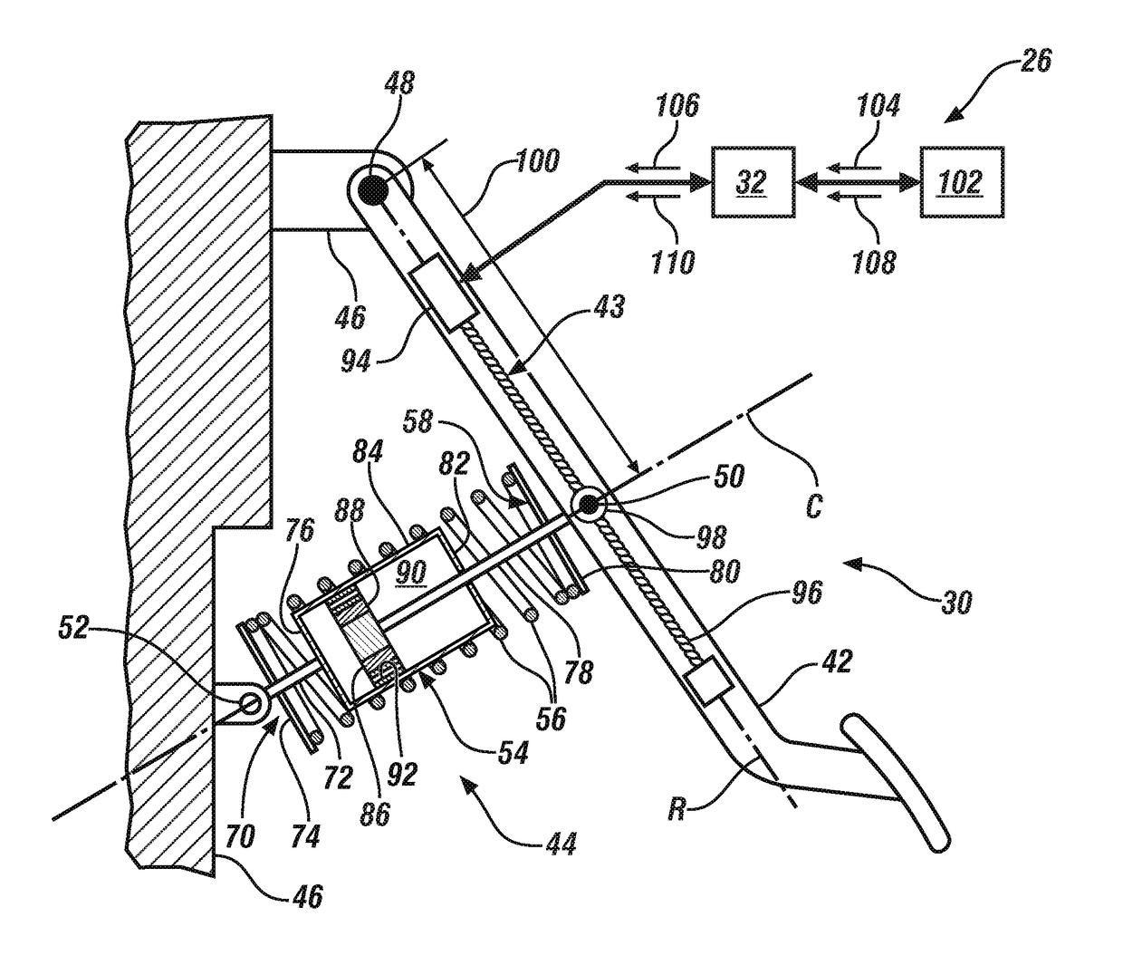
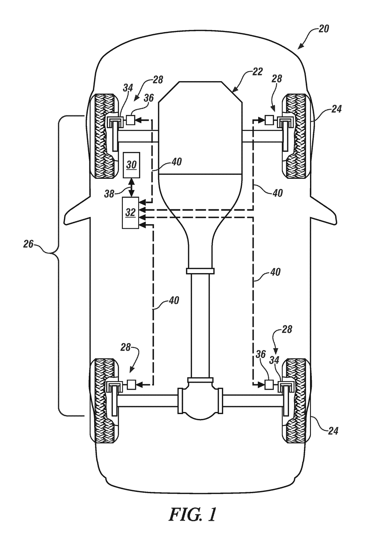
[0017]In accordance with an exemplary embodiment of the invention, FIG. 1 is a schematic of a vehicle 20 that may include a powertrain 22 (i.e., an engine, transmission and differential), a plurality of rotating wheels 24 (i.e., four illustrated), and a braking system 26 that may be a BBW system as one, non-limiting, example. The BBW...


PUM


Abstract

A brake pedal assembly of a braking system for a vehicle includes a brake pedal pivotally engaged to a support structure at a first pivot axis. A linkage of the brake pedal assembly is pivotally engaged to the brake pedal at a second pivot axis spaced from the first pivot access by a distance. An adjustment mechanism of the assembly is carried by the brake pedal and is constructed and arranged to alter the distance.

Description

FIELD OF THE INVENTION[0001]The subject invention relates to a vehicle braking system, and more particularly, to an adjustable brake pedal assembly of the braking system.BACKGROUND[0002]Traditional service braking systems of a vehicle are typically hydraulic fluid based systems actuated by a driver depressing a brake pedal that generally actuates a master cylinder. In-turn, the master cylinder pressurizes hydraulic fluid in a series of hydraulic fluid lines routed to respective actuators at brakes located adjacent to each wheel of the vehicle. Such hydraulic braking may be supplemented by a hydraulic modulator assembly that facilitates anti-lock braking, traction control, and vehicle stability augmentation features. The wheel brakes may be primarily operated by the manually actuated master cylinder with supplemental actuation pressure gradients supplied by the hydraulic modulator assembly during anti-lock, traction control, and stability enhancement modes of operation.[0003]When a p...

Claims


Application Information

Patent Timeline
IPC IPC(8): B60T7/06
CPCB60T7/06F16H2025/2043F16H25/2204B60T7/042B60T8/3255
Inventor PENNALA, BRANDON C.KRUEGER, ERIC E.KILMURRAY, PAUL A.
Owner GM GLOBAL TECH OPERATIONS LLC
Why Eureka
Try Eureka